background image

Command reference

R&S

®

ZNB/ZNBT

1295

User Manual 1173.9163.02 ─ 62

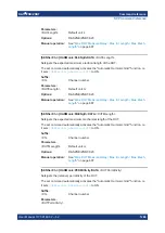
[SENSe<Ch>:]POWer:GAINcontrol 

<ReceiverName>, <Mode>

[SENSe<Ch>:]POWer:GAINcontrol? 

<ReceiverName>

Defines port-specific gain settings for the related channel.

Note:

These settings will only take effect if 

[SENSe<Ch>:]POWer:GAINcontrol:

GLOBal

 is set to 

MANual

 for channel <Ch>.

Without the 

Extended power range

 option only the gain of the measurement receiv-

ers (the b-waves) can be statically set (to LNOise or LDIStortion); the reference
receiver always uses automatic gain control (AUTO). With the option available,
also the gain of the reference receivers (the a-waves) can be set statically.

If you also want to distinguish between different sweep segments, use

[SENSe<Ch>:]SEGMent<Seg>:POWer:GAINcontrol

 instead.

Suffix: 

<Ch>

.

Channel number

Parameters:

<Mode>

AUTO | LDIStortion | LNOise

AUTO

automatic/adaptive gain control (AGC) according to the RF input
level

LDIStortion

fixed, small IF gain, for high input levels

LNOise

fixed, large IF gain, for low input levels
*RST: 

LDIStortion

Parameters for setting and query: 

<ReceiverName>

String parameter defining the wave(s) followed by the drive port;
see examples below and 

Table 7-4

.

Example: 

*RST; :SENSe:POWer:GAINcontrol:GLOBal MANual

Activate independent GC settings for each drive port.

SENSe:POWer:GAINcontrol 'B2D1', LNO

Set the GC for the received wave b

2

 (port 2) to "Low Noise". The

setting applies while port 1 is the drive port.

SENSe:POWer:GAINcontrol 'A2B2B3D2', LNO

Set the GC mode for the waves a

2

, b

2

, and b

3

 to "Low Noise".

The setting applies while port 2 is the drive port.

SENSe:POWer:GAINcontrol? 'B1D2'

Query the GC setting for the wave b

1

 while port 2 is the drive

port. The response is 

1, LDIS

 (default setting).

Manual operation: 

See 

"Drive-port specific settings"


on page 581

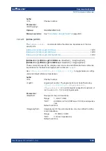
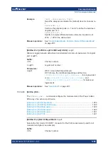
[SENSe<Ch>:]POWer:GAINcontrol:ALL 

<Mode>

Applies the same manual gain control (GC) <Mode> to all a and b wave receivers.

SCPI command reference

Содержание ZNB Series

Страница 1: ...R S ZNB ZNBT Vector Network Analyzers User Manual 1173916302 Version 62 2...

Страница 2: ...ports order no 1311 6010K72 R S ZNB40 100 kHz to 40 GHz 2 test ports order no 1311 6010K82 R S ZNB40 100 kHz to 40 GHz 4 test ports order no 1311 6010K84 R S ZNB43 100 kHz to 43 5 GHz 2 test ports 2 9...

Страница 3: ...ets and brochures 22 2 2 7 Release notes and open source acknowledgment OSA 22 2 2 8 Application notes application cards white papers etc 22 3 Getting started 23 3 1 Preparing for use 23 3 1 1 Lifting...

Страница 4: ...8 3 4 1 Transmission S parameter measurement 78 3 4 2 Reflection S parameter measurement 85 4 Concepts and features 87 4 1 Basic concepts 87 4 1 1 Global persistent settings 87 4 1 2 Recall sets 88 4...

Страница 5: ...s 202 4 6 Offset parameters and de embedding 202 4 6 1 Offset parameters 202 4 6 2 Embedding and deembedding 208 4 7 Optional extensions and accessories 221 4 7 1 Additional test ports R S ZNBT only 2...

Страница 6: ...with ESD limiters 262 4 7 25 DC inputs 262 4 7 26 USB to IEC IEEE adapter 265 4 7 27 External power meters 265 4 7 28 External generators 267 4 7 29 External switch matrices 269 4 7 30 External DLLs 2...

Страница 7: ...ace Statistics tab 355 5 5 9 Smooth Shift Hold tab 361 5 5 10 Infinite Averaging tab 364 5 5 11 Trace Data tab 365 5 6 Lines softtool 373 5 6 1 Limit Test tab 373 5 6 2 Ripple Test tab 381 5 6 3 Circl...

Страница 8: ...l softtool 445 5 11 1 Start Cal tab 446 5 11 2 Cal Devices tab 511 5 11 3 Pwr Cal Settings tab 524 5 11 4 Use Cal tab 531 5 11 5 METAS Cal tab 538 5 12 Channel Config softtool 547 5 12 1 Channels tab...

Страница 9: ...dditional Simulation Data dialog 678 5 15 DUT Softtool 681 5 16 Applic softtool 681 5 16 1 External Tools application 682 5 16 2 TDR application 683 5 16 3 DUT Centric application 711 5 16 4 Distance...

Страница 10: ...ces in remote control 818 6 3 3 Initiating measurements speed considerations 819 6 3 4 Addressing traces and channels 820 6 4 Command processing 821 6 4 1 Input unit 821 6 4 2 Command recognition 822...

Страница 11: ...Mory commands 1136 7 3 11 MMEMory commands 1138 7 3 12 OUTPut commands 1178 7 3 13 PROGram commands 1183 7 3 14 SENSe commands 1186 7 3 15 SOURce commands 1331 7 3 16 STATus commands 1380 7 3 17 SYSTe...

Страница 12: ...ing firmware operation 1528 9 1 1 Asynchronous errors 1529 9 1 2 Errors during measurement 1529 9 2 Errors during firmware installation update 1530 9 3 Collecting information for technical support 153...

Страница 13: ...Contents R S ZNB ZNBT 13 User Manual 1173 9163 02 62 12 4 Showroom mode 1554 12 5 ENA emulation commands 1555 Glossary Frequently used terms 1563 List of commands 1569 Index 1596...

Страница 14: ...Contents R S ZNB ZNBT 14 User Manual 1173 9163 02 62...

Страница 15: ...tions Products from the Rohde Schwarz group of companies are manufactured according to the highest technical standards To use the products safely follow the instructions provided here and in the produ...

Страница 16: ...or different positions secure the product so that it cannot fall over If the product has foldable feet always fold the feet completely in or out to ensure sta bility The feet can collapse if they are...

Страница 17: ...er source at any time Pull the power plug to disconnect the product The power plug must be easily accessible If the product is integrated into a system that does not meet these requirements provide an...

Страница 18: ...The sig nal word indicates the severity of the safety hazard and how likely it will occur if you do not follow the safety precautions WARNING Potentially hazardous situation Could result in death or...

Страница 19: ...dicated softtool tab and dock widget simplify common deembedding scenarios See Chapter 5 13 11 Deembed Assistant tab on page 652 Note that the deembedding assistant requires at least one of the relate...

Страница 20: ...B ZNBT B4 No OCXO Cold warning if the reference frequency quartz was not on working temperature Was only displayed with developer service level 3 Time domain analysis R S ZNB ZNBT K2 Selecting a diffe...

Страница 21: ...he contents of the user manual are available as help in the R S ZNB ZNBT The help offers quick context sensitive access to the complete information for the instrument and its firmware The user manual...

Страница 22: ...https www rohde schwarz com brochure datasheet ZNBT 2 2 7 Release notes and open source acknowledgment OSA The release notes list new features improvements and known issues of the current firmware ver...

Страница 23: ...to the handles See Lifting and carrying the product on page 15 3 1 2 Unpacking and checking 1 Unpack the R S ZNB ZNBT carefully 2 Retain the original packing material Use it when transporting or shipp...

Страница 24: ...It is therefore not suitable for class B environments If class A equipment causes radio disturbances take appropriate measures to eliminate them 3 1 4 Setting up the product See also Setting up the p...

Страница 25: ...ing up the product on page 16 2 NOTICE Insufficient airflow can cause overheating and damage the product Design and implement an efficient ventilation concept for the rack To mount the R S ZNB ZNBT in...

Страница 26: ...connected external devices comply with EMC regulations Regarding length and quality the following requirements have to be met for cable that are directly connected to the R S ZNB ZNBT Table 3 1 Cable...

Страница 27: ...ty information see Connecting to power on page 16 The network analyzer is automatically adapted to the AC supply voltage which must be in the range of 100 V to 240 V at 50 Hz to 60 Hz A line frequency...

Страница 28: ...panel R S ZNB on page 47 or Chapter 3 2 4 Rear panel R S ZNBT on page 49 After power on the analyzer automatically goes to standby or ready state depend ing on the state of the standby toggle key at...

Страница 29: ...Frequency Reference In this state it is safe to switch the AC power off and disconnect the instrument from the power supply In ready state all modules are power supplied When switched to ready state t...

Страница 30: ...rly creates security updates and other patches to protect Windows based operating systems They are released through the Microsoft Update website and associated update server Update instruments using W...

Страница 31: ...2 In the Shortcut tab select Run Minimized A software update restores the original shortcut properties 3 1 11 Connecting external accessories The analyzer s standard PC interfaces Monitor USB LAN can...

Страница 32: ...lication window to add the virtual Hard Key Panel to the application window Changing the Screen Resolution R S ZNBT In case the R S ZNBT fails to adjust the display resolution properly when an externa...

Страница 33: ...by the operating system it can safely be disconnected and reconnected even dur ing measurements Mouse configuration Select Settings Devices Mouse touchpad from the Windows Start menu to configure the...

Страница 34: ...cable can be connected to the LAN connector on the rear panel of the analyzer To establish a LAN connection proceed as follows 1 Refer to Chapter 3 1 12 1 Assigning an IP address on page 35 2 Connect...

Страница 35: ...ot support DHCP or if the analyzer is set to use alternate TCP IP configuration the addresses must be set manually By default the analyzer is configured to use dynamic TCP IP configuration and obtain...

Страница 36: ...the local connection Windows 7 open the Control Panel Network and Internet Network and Sharing Center Local Area Connection Status dialog 5 Select Properties and confirm the user account control messa...

Страница 37: ...ument name is a case insensitive string with the following syntax ZNB 4 8 20 26 40 43 variant serial_number ZNB40 N serial_number ZNBT8 8 serial_number ZNBT 20 26 40 1 serial_number The serial number...

Страница 38: ...connected at the time you log in to the instrument via remote desktop Windows possibly displays the following error message This message can be safely ignored 3 1 12 4 Windows firewall settings A fir...

Страница 39: ...out the firewall refer to the Windows Help 3 2 Instrument tour This chapter gives an overview of the control elements and connectors of the R S ZNB ZNBT and gives all information that is necessary to...

Страница 40: ...ing system can be used to switch off the display if the analyzer receives no command for a selectable period of time The display is switched on again if any front panel key is pressed To enable the sc...

Страница 41: ...arameters to shift the measurement plane The STIMULUS keys START STOP CENTER SPAN define the sweep range depending on the sweep type The SYSTEM keys provide general system settings FILE provides stand...

Страница 42: ...er the letters G M K respectively x1 is equivalent to ENTER and confirms the previous entry ESC is used to Cancel entries close dialogs without activating the entries made equivalent to the Close butt...

Страница 43: ...Navigate between table columns in diagrams Press OK to toggle between navi gation mode and data entries Compress or expand menus or the Help table of contents Move the highlighted item in the menu bar...

Страница 44: ...cond source For the R S ZNBT an internal second source is automatically added if the instrument is equipped with 12 ports or more Use a torque wrench when screwing RF cables on the test port connector...

Страница 45: ...s serve as outputs for the RF stimulus signal and as inputs for the mea sured RF signals from the DUT response signals With a single test port it is possible to generate a stimulus signal and measure...

Страница 46: ...ded on the front panel They can be used to connect External PC accessories such as mouse or other pointing devices a keyboard printer or external storage device USB stick CD ROM drive etc External mea...

Страница 47: ...rview of the rear panel controls and connectors of the net work analyzer 1 2 12 3 4 5 8 13 11 14 7 6 9 10 15 16 17 1 2 12 3 4 5 8 13 11 14 7 6 9 10 15 16 17 Figure 3 4 R S ZNB rear view top 1st genera...

Страница 48: ...See Chapter 3 1 11 1 Connecting a monitor on page 32 7 USER PORT 25 pin D Sub connector used as an input and output for low voltage 3 3 V TTL control signals See Chapter 12 3 1 1 User Port on page 153...

Страница 49: ...System Power Management Interface Specification 10 General Purpose Input Output GPIO pins See Chapter 4 7 19 RFFE GPIO interface on page 257 14 Device Control Option R S ZNB B12 Device Control provid...

Страница 50: ...wo additional type A USB 3 0 host connectors similar functionality as the type A USB host connectors on the front panel see USB Connectors on page 46 5 Monitor Display Port External monitor connector...

Страница 51: ...ace on page 256 Table 3 5 Optional rear panel connectors Index Label Description 15 DC INPUT Option R S ZNBT B81 DC Inputs provides four BNC inputs for DC measurements adjustable to different voltage...

Страница 52: ...unctions are accessible via several tabbed softtools each presenting related functions and settings The function keys on the front panel R S ZNB only or the on screen Hard Key Panel open the most freq...

Страница 53: ...softtool panel to your preferred position see Chapter 3 3 5 4 Using drag and drop on page 69 For example you can show hide the on screen hardkey panel by selecting deselecting Display View Bar Hard K...

Страница 54: ...at the bottom of the application screen provides alternative access to all instrument functions To repeat the measured quantity selection described above Select Trace Meas Z Sij Z S11 The diagram imme...

Страница 55: ...Getting started R S ZNB ZNBT 55 User Manual 1173 9163 02 62 2 Select S Parameter to open the Meas S Params softtool tab 3 Select Z Sij Z S11 Operating the instrument...

Страница 56: ...vides all settings Using the menus and submenus of the menu bar alternative to the previous method Using the context menus of certain display objects for important actions in the context of this objec...

Страница 57: ...also available via the menu bar items System Undo Redo Undo reverses the last action redo reverses the last undo action if possi ble These icons control the zoom function Trace Scale Zoom If multiple...

Страница 58: ...ng and or deleting diagrams a breeze Toggle other measurements except the active trace OFF ON Open the METAS Reconnection dialog This button is only visible if option R S ZNB ZNBT K50 Measure ment Unc...

Страница 59: ...des functions to handle recall sets and trace files to print or save diagram content and to shut down the VNA application The Trace menu provides all trace settings the limit check settings and the ma...

Страница 60: ...a dialog to define the search range for the marker search A menu command with no arrow or dots initiates an immediate action Example Max sets the active marker to the maximum of the active trace 3 3 2...

Страница 61: ...bar The status bar shows the active channel the current channel s sweep averaging counter e g Ch i Avg 9 10 or Ch i Avg None if averaging is disabled the progress of the sweep The progress bar also s...

Страница 62: ...tware using various finger gestures on the screen The basic gestures supported by the software and most applications are described here Further actions using the same gestures may be possible Tapping...

Страница 63: ...ngers in the display you graphi cally zoom in vertically When you pinch two fingers in the display you graphically zoom out vertically Figure 3 12 Pinching While Zoom Select is active toolbar icon or...

Страница 64: ...a Change hardware settings Spread and pinch two fingers Mouse wheel to scroll up or down Swipe Dragging scrollbars to scroll up or down left or right Swipe In graphical zoom mode only dragging the bor...

Страница 65: ...he dialog visible Note The Dialog Transparency is a global setting i e it applies to all dialogs Use the icon to create a screenshot of the dialog Drag and drop the lower right corner of the dialog to...

Страница 66: ...elements 3 3 5 1 Adding new traces and diagrams A new trace is required if you want to measure and display an additional quantity Typical scenario The transmission coefficient S21 is measured as desc...

Страница 67: ...as Drag and drop a softkey repre senting a measured quantity to create a trace Or simply select another softkey to change the measured quantity of the active trace Select Trace Trace Config to access...

Страница 68: ...kers traces diagrams and other display elements are most conveniently deleted using the Delete icon in the toolbar above the diagram area To delete a single marker drag it into vertical direction to r...

Страница 69: ...e Separator between adjacent diagrams Delete See Chapter 3 3 5 3 Deleting display elements on page 68 Trace Create See Chapter 3 3 5 1 Adding new traces and diagrams on page 66 Move vertically Referen...

Страница 70: ...point Use to change the sign of the value Use G n M k m or x1 to multiply the entered value with factors of 10 9 10 6 10 3 or 1 and to add the appropriate physical unit To enter a character string 1 T...

Страница 71: ...uttons in the numeric keypad to compose the numeric input value 3 If desired select a Step Size and use the cursor up down buttons to increment decrement the current value If a marker is active you ca...

Страница 72: ...selection and close the keyboard 3 3 6 4 Using the Windows on screen keyboard The Windows on screen keyboard allows you to enter characters in particular letters even if an input field cannot call up...

Страница 73: ...olar diagrams it is not available To activate the graphical zoom Select the Zoom Config icon in the toolbar above the diagram area and make sure that the graphical zoom mode is active Select the Zoom...

Страница 74: ...On in the Zoom softtool tab toggles an overview The upper part of the diagram then shows a small version of the unzoomed diagram You can move the zoomed part of the trace by moving the rectangular are...

Страница 75: ...Div modifies the value of the vertical or radial diagram divi sions and thus the entire range of response values displayed The Scale Div and the Ref Value are indicated in the scale section of the tra...

Страница 76: ...nd select the parameter from the context menu Select the parameter from the Trace Scale menu Use the Set by Marker functions see Chapter 3 3 7 6 Set by marker on page 76 3 3 7 6 Set by marker The Set...

Страница 77: ...ax Marker to move the trace towards the upper diagram edge leaving the values of the vertical divisions Scale Div and the overall vertical scale unchanged Analogously select Min Marker to move the tra...

Страница 78: ...sweep range 5 Adjust the receiver and source settings measurement bandwidth source power 6 Perform a calibration 3 4 1 Transmission S parameter measurement In a transmission measurement the analyzer t...

Страница 79: ...19 20 21 22 23 24 17 DUT 1 2 VNA 1 Connect the DUT between test ports 1 and 2 of the network analyzer as shown above 2 Use the Preset key to restore a well defined instrument state The analyzer is no...

Страница 80: ...e stimulus signal from the analyzer port no 2 is not needed except for some calibration types By default the sweep range is set to the frequency range of the analyzer which can be unsuitable for your...

Страница 81: ...expected system errors the accuracy requirements of the measurement on the test setup and on the types of calibration standards available The following example requires a calibration kit with a male T...

Страница 82: ...ion is replaced by a generic port list The selection logic is unchanged 4 Select Next to proceed to the next page of the Calibration Setting wizard 5 Select the test port connector type and gender her...

Страница 83: ...NBT has completed the calibration sweep and calculated the correction data the Apply button is enabled 8 Select Apply to close the wizard The system error correction is calculated and applied to the c...

Страница 84: ...hoose the Delay of the transmission coefficient as displayed quantity The group delay represents the propagation time of the wave through the DUT it is displayed in a Cartesian diagram The marker info...

Страница 85: ...ows clipboard 6 Select System File Recall Sets Save to open the Save dialog for recall sets 7 In the Save dialog a Select a file location Look in b Enter a name for the recall set file File name c Sel...

Страница 86: ...zard and select an appropriate type A full n port calibration TOSM UOSM TNA corrects the system errors for all transmission and reflection S parameters Some of the trace formats are particularly suite...

Страница 87: ...ptimize the evaluation of results To ensure that the instrument resour ces are easily accessible and that user defined configurations can be conveniently implemented stored and reused the instrument u...

Страница 88: ...ecall sets A recall set only contains setup instructions i e information on how to measure how to process the measurement results and how to display the processed results It does not contain any trace...

Страница 89: ...settings can be accessed via the keys in the Trace section of the virtual hardkey panel They complement the Channel settings accessible via the Stimulus and Channel sections Each trace is assigned to...

Страница 90: ...hlighted Channels with no traces are not indicated in the diagrams but can be accessed via the Channel Manager dialog In manual control there is always exactly one active trace irrespective of the num...

Страница 91: ...ve port is used Each sweep point requires a single partial measurement See also Chapter 4 3 1 S parameters on page 125 For a complete two port S parameter measurement e g S11 S21 S12 S22 the analyzer...

Страница 92: ...mode Sweep Trigger event starts n partial sweeps over all sweep points Trigger event starts m complete measurements at consecutive sweep points Sweep Segment Trigger event starts n partial sweeps ove...

Страница 93: ...Ch1 HW Sweep Ch2 HW Sweep Ch3 HW Sweep Ch1 Sweep End Ch2 Sweep End Ch3 Sweep End Ch1 Calc Ch1 Results Ch2 Calc Ch2 Results Ch3 Calc Ch3 Results Figure 4 2 Pipelining In the current implementation setu...

Страница 94: ...ultiple DUTs can be measured in parallel using the same stimu lus settings 2 3 4 5 6 7 8 9 10 11 12 13 14 15 16 1 18 19 20 21 22 23 24 17 DUT1 DUT2 VNA For analyzers with Internal second source to red...

Страница 95: ...l second source it is possible to specify a minimum frequency offset between the port groups This is particularly useful for situations where Crosstalk between different DUTs would otherwise make the...

Страница 96: ...unit Stop unit Center unit Span unit Lin Freq Start Frequency Hz Stop Frequency Hz Center Frequency Hz Span Frequency Hz Log Freq Start Frequency Hz Stop Frequency Hz Segmented Power Start Power dBm S...

Страница 97: ...analyzer In arbitrary mode with option R S ZNB ZNBT K4 you can define port specific fre quencies and powers see Chapter 5 12 2 2 Port Settings dialog on page 562 4 1 4 5 Stepped vs swept mode The R S...

Страница 98: ...de is generally higher DUTs with long group delay cannot be measured correctly in swept mode It is essential to perform the Calibration with the same stepped swept mode set tings as for the actual mea...

Страница 99: ...bedding Wave quantities without wave de embedding SYSTEM ERROR CORRECTION Factory 0 a b 1 2 3 Data access points 0 Raw wave quantities 1 Factory calibrated S parameters 2 S parameters 3 Balanced symme...

Страница 100: ...he new wave de embedding remains in the wave quantity conductance domain and calculates all de embedding steps in one multiplication step without unnecessary matrix inversions With wave de embedding t...

Страница 101: ...Export complex data with trace math 6 Export formatted data SHIFT RESPONSE TIME DOMAIN GATE TRACE FORMAT SMOOTH SHIFT HOLD Formatted TRACE MATH DISPLAYED QUANTITY 6 5 Requires Time Domain option Befo...

Страница 102: ...ti cally unlimited number of traces which can be assigned to different channels Most diagram settings are arranged in the Display softtool hardkey System Dis play To assign traces and channels to diag...

Страница 103: ...page 104 A trace can be either a data trace a memory trace or a mathematical trace see Trace types on page 103 Trace types The analyzer uses traces to display the current measurement result in a diag...

Страница 104: ...ts The format section shows how the measured data is presented in the graphical display Use the context menu of the format section to change the format of the related trace The next sections show the...

Страница 105: ...t the end of the trace line if the system error correction no longer applies to the trace 4 2 1 3 Markers Markers are tools for numerical readout of measured data and for selecting points on the trace...

Страница 106: ...or specific points on the trace Marker Search Target Search Bandfil ter Activating and moving markers To activate a marker either select the marker symbol itself or the corresponding line in the marke...

Страница 107: ...eld To change the position appearance or contents of the marker info field use one of the following methods The info field can be moved to several positions in the upper and lower part of the active d...

Страница 108: ...format of the related trace For a trace s default marker format this means that the default format is dynamically adjusted according to the selected trace for mat Lin Mag Magnitude of z unconverted z...

Страница 109: ...n the Trace Config Format softtool An impedance Z is represented as Z R jX the corresponding admittance as Y 1 Z G jB For X 0 we have an inductance L X for X 0 we have a capaci tance C 1 X where denot...

Страница 110: ...he search is activated the active marker is moved to the next point that meets the search criteria If the trace contains no markers a marker M1 is created and used for the search The search result is...

Страница 111: ...lose if the bandwidth is small compared to the geometric mean of the band edges Lower Edge is the closest frequency below the maximum or minimum where the trace value is equal to the maximum minimum v...

Страница 112: ...channel e g the measurement at arbitrary port frequencies Arb Port n Start indicates the lowest value of the sweep variable e g the lowest frequency measured corresponding to the left edge of a Carte...

Страница 113: ...nnel name section sweep range sec tion additional parameter section To open a context menu associated with a display element tap and hold R S ZNB only or right click the element for some seconds Examp...

Страница 114: ...ularly useful when a numeric value is incremented or decremented or when display elements are added or removed In most dialogs however it is possible to cancel an erroneous input before it takes effec...

Страница 115: ...down list are provided for easy navigation in the file system place the cursor on the icons to obtain Whats this help Windows Explorer opens the selected directory in the Windows Explorer File name s...

Страница 116: ...ut saving the data Windows Explorer opens the selected directory in Windows Explorer If Ask Before Overwriting is enabled overwriting an existing file has to be con firmed Tip Dialog properties e g th...

Страница 117: ...nse to the stimulus value frequency power or time The response can be calculated from the measured quantity at the related stimulus value but it can also be the result of some mathematical transforma...

Страница 118: ...o hold for real measurement values y 0 Trace Format Description Formula dB Mag Magnitude of z in dB dB Mag z 20 log z dB Phase Phase of z z arctan y x SWR Voltage Standing Wave Ratio SWR 1 z 1 z Lin M...

Страница 119: ...esponse val ues and that is graphically overlaid to the formatted trace Polar For Polar traces the complex response values are represented in polar coordinates magnitude and phase In a diagram the gri...

Страница 120: ...d represented in terms of their corresponding complex impedance Z Sii R Sii j X Sii In a diagram the grid lines overlaid to a Smith trace correspond to points of equal resistance R and reactance X Poi...

Страница 121: ...components of the impedance respectively Example Reflection coefficients in the Smith chart If the measured quantity is a complex reflection coefficient e g S11 S22 then the unit Smith chart can be u...

Страница 122: ...e of the reflection coefficient of a short circuit Z 0 U 0 is one its phase is 180 deg Inv Smith For Inv Smith formatted traces the response values are interpreted as complex reflection coefficients S...

Страница 123: ...ce is infinity short and zero open The outer circle corresponds to zero conductance purely imaginary admittance Points outside the outer circle indicate an active component The upper and lower half of...

Страница 124: ...y The arcs for the points of equal susceptance also belong to circles intersecting at Y infinity short circuit point 1 0 centered on a straight vertical line Examples for special points in the inverte...

Страница 125: ...tors DC 1 4 PAE Lin Mag ON ON default for Z parameters Y param eters impedances admittances ON default dB Mag ON default ON default for wave quantities Phase ON ON Real ON ON ON Imag ON ON Unwrapped P...

Страница 126: ...rpreted as follows S11 is the reflection coefficient of DUT port 1 i e the ratio between outgoing wave b1 and incident wave a1 in a forward measurement with matched DUT port 2 S11 b1 a1 if a1 0 and a2...

Страница 127: ...and input ports of a DUT the parameters are referred to as single ended S parameters The S parameter description can also be used to differentiate between different propagation modes of the waves at t...

Страница 128: ...ical Port 2 a wave a4 b wave b4 Source Port 4 1 4 Figure 4 7 Two redefined ports High Signal Power When dealing with external signal amplification make sure that the signals fed to the analyzer are wi...

Страница 129: ...at least one test port has a non zero imaginary part Conversion formula for wave quantities and S parameters Renormalization transforms the raw S matrix S0 for the default reference impedances Z0i wi...

Страница 130: ...mpedance parameter is obtained from a single S parameter Z parameters complete description of an n port DUT 4 3 3 1 Converted impedances The converted impedance parameters Zij 1 i j n describe the inp...

Страница 131: ...scribes a one port DUT The calculation formula of the converted reflection impedances Zii depends on the waveguide circuit theory according to which Reference impedances are calculated Table 4 4 Calcu...

Страница 132: ...converted parallel transmission impedance Zij depends on the waveguide circuit theory according to which Reference impedances are calculated Table 4 6 Calculation of Converted Parallel Transmission Im...

Страница 133: ...as Zij where i denotes the measured and j the stimulated port The Z parameters for a two port are based on a circuit model that can be expressed with two linear equations 2 22 1 21 2 2 12 1 11 1 I Z I...

Страница 134: ...h output ports terminated in a short circuit voltage 0 The analyzer provides the full set of Y parameters including the transfer admittances i e the complete n x n Y matrix for an n port DUT This mean...

Страница 135: ...s provide the complex ratio of any combination of transmitted or received wave quantities In contrast to S Z and Y parameters wave quantities and ratios are not system error corrected To increase the...

Страница 136: ...nts or non recipro cal devices do not allow a system error correction so that a complete S parameter measurement is not possible The test setup contains frequency converting components so that the tra...

Страница 137: ...or More Ratios dialog It calculates the arithmetic mean of the magnitude and phase values of these results separately Combining different detectors The detector setting in the More Ratios menu applies...

Страница 138: ...DUT VNA 1 2 DUT Balanced port Internal balance unbalance conversion Logical VNA ports Unbalance balance conversion avoids the disadvantages of real transformers There is no need to fabricate test fixt...

Страница 139: ...ode Zref Z0c Balanced port Log VNA port A balanced port configuration is defined in two steps First select the pairs of physical ports that you want to combine to form balanced ports Second define the...

Страница 140: ...ined as the ratio of the wave quantities b1 mode mout reverse measurement with matched input b1 in the figure above and a1 0 to a2 mode min S mout min 22 is the mixed mode output reflection coefficien...

Страница 141: ...e deviation of the balun from ideality The general definition of the transmission imbalance between two differ ent ports at least one of them balanced is given below For a DUT with two balanced ports...

Страница 142: ...r i j CMRRji Sddji Sccji Differential Imbalance A differential imbalance can also be calculated if the second balanced DUT port is connected to two single ended logical ports DUT Balanced port Balance...

Страница 143: ...meter IEEE Trans MTT vol 40 No 12 pp 2303 2311 Dec 1992 4 3 8 Group delay The group delay g represents the propagation time of wave through a device g is a real quantity and is calculated as the negat...

Страница 144: ...d accessories on page 221 The R S ZNB ZNBT can also check whether the measured values comply with speci fied limits and export trace data using different file formats 4 4 1 Limit check A limit line re...

Страница 145: ...does not have to be smaller than the Start Stimulus value of segment no n 1 Overlapping segments are allowed The limit check in the overlapping area is rela ted to the tighter limit the pass test invo...

Страница 146: ...imit Line is active the diagrams display all limit line segments Exception In a segmented frequency sweep with point based x axis gaps between the segments are minimized To facilitate the interpretati...

Страница 147: ...s not have to be smaller than the Start Stimu lus value of range no n 1 Overlapping ranges are allowed The limit check in the overlapping area is related to the tighter limit the pass test involves a...

Страница 148: ...line which is defined by its center coordi nate in the diagram and its radius Depending on the diagram type circle limit can serve different purposes With a circle limit line centered on the origin of...

Страница 149: ...User Manual 1173 9163 02 62 With a circle limit line centered on the left border of an inverted Smith diagram Y infinity you can check whether the imaginary part of the admittance Im Y sus ceptance fa...

Страница 150: ...e has the extension limit and is stored in the directory shown in the Save Limit Line and Recall Limit Line dialogs The file starts with a preamble containing the channel and trace name and the header...

Страница 151: ...ng lines contain the entries of all editable columns of the list Example of a ripple limit file The ripple limit list is described by the ripple limit file Compatibility with other instruments The VNA...

Страница 152: ...n is the number of network ports The following displays an s1p export file in Version 1 1 ZNx format HZ S RI R 50 00 Rohde Schwarz Vector Network Analyzer Rohde Schwarz ZNB8 4Port 1311601044100019 3 2...

Страница 153: ...rt if the impedances of all involved ports are identical the analyzer sets the reference resistance to the real part of this impedance Other wise it sets it to 50 With the exception of the opening sym...

Страница 154: ...ference impedance of this file While reading the file the reference impedance value of the option line above is always used For more information see Renormalization of S parameters on page 159 For the...

Страница 155: ...or export formats Version 1 1 and Version 2 0 they are declared in a dedicated comments section Port Assignments Nominal Port Actual Test Port 1 2 2 1 For balanced ports the port assignment looks like...

Страница 156: ...cies Number of Frequencies 201 Number of exported frequency sweep points can also be derived from the Network parameter data block Reference Reference 50 75 If the exported S parameter data were renor...

Страница 157: ...ding order of frequency For segmented sweeps the R S ZNB ZNBT makes an exception to the strict ascend ing order principle During export the segments are always kept together which can result in downwa...

Страница 158: ...rom a single trace Typically Touchstone files contain a complete set of S parameter traces of an n port network The only exceptions are s1p files created from arbitrary S parameter traces using the s1...

Страница 159: ...file into standard applications including the R S ZNB ZNBT itself the reference resistance of the Touchstone option line is used and the impedance system underlying the data is not interpreted cor rec...

Страница 160: ...2 3 Finding the best file format The file format depends on how you want to use the exported data Use a Touchstone file format to export S parameter data traces to a file that can be evaluated with a...

Страница 161: ...ialize and finished by a COMMit 1 Initialize the shared memory buffer SYSTem DATA MEMory INITalize 2 Add traces a SYSTem DATA MEMory ADD TrName1 FDATA SDATa Values1 Select an existing trace name choos...

Страница 162: ...pes the magnitude and phase response of each calibration standard i e its S parameters if no system errors occur must be known within the entire sweep range In some calibration procedures TRL TNA TRM...

Страница 163: ...cy Offset settings and the Fre quency Offset settings that were used during calibration see Parallel Measure ments with Frequency Offset on page 95 There is a mismatch between the current sweep mode s...

Страница 164: ...to high Unidirectional trans mission measure ments in any direc tion and between any combination of ports TOSM or UOSM n port Open Short Match1 at each port Through2 between all port pairs All Reflect...

Страница 165: ...s on standards Reflection and transmission mea surements espe cially for planar cir cuits 1 Or any other 3 known one port standards To be used in a guided calibration the known standards must be decla...

Страница 166: ...nal Complementary Match standard measurements For reflection normalizations the mandatory Open or Short measurements can be complemented by optional Match measurements Additionally measuring a Match s...

Страница 167: ...4 5 1 4 TOSM and UOSM calibration TOSM A TOSM Through Open Short Match calibration requires the same standards as the one path two ports calibration however all measurements are performed in the for w...

Страница 168: ...es at its test ports to mea sure DUTs with different port connectors see also Chapter 4 5 1 5 Adapter removal on page 168 If the same connector types are used but an appropriate Through standard is no...

Страница 169: ...2 Figure 4 9 Adapter Removal vs UOSM The obtained adapter characteristics are mathematically removed from the obtained error coefficients Uncertainties arising from a non ideal characterization of the...

Страница 170: ...alibration requires a low reflection low loss Through standard with an electrical length that can be different from zero a Reflect and a Match The magnitude of the reflection coefficient of the Reflec...

Страница 171: ...main where TRL becomes inaccurate replace TRL by TRM calibration See Low frequency extension with TRM on page 172 The methods can be combined or used separately The list of measured standards in the c...

Страница 172: ...ed if flong fshort For a TRL calibration using three Lines with different length the allowed frequency ranges are calculated in an analogous manner to obtain three ideally overlapping fre quency range...

Страница 173: ...its reflection coefficient can be unknown but must be nonzero Its phase must be roughly known 90 deg The magnitude and phase of the reflection coefficient must be the same at both test ports The Atte...

Страница 174: ...required an Automatic calibration always proposes a minimum number of port assignments However for each port assignment all possible through connections are measured by default If you want to apply th...

Страница 175: ...ious subdialogs Calibration kits and connector types are global resources the parameters are stored independently and are available irrespective of the current recall set 4 5 2 1 Calibration standard...

Страница 176: ...calibration The default characteristic impedance is equal to the reference impedance of the system The loss is the energy loss along the transmission line due to the skin effect For resistive lines an...

Страница 177: ...ort standard which is fully matched in both directions the reflection factor at both ports is zero No load and offset parameters need to be set 4 5 2 2 Cal kit parameter types The analyzer uses three...

Страница 178: ...rt GHz or 0 G s in Keysight mode All inductance and capacitance parameters are set to zero 4 5 2 3 Sliding Match standards The Sliding Match is a one port standard consisting of an air line with a mov...

Страница 179: ...frequencies above the Min Freq In general the Sliding Match provides better results than the Match within its specified fre quency range 4 5 2 4 Cal kit Files Calibration kit files can be used to sto...

Страница 180: ...export csv cal kit files The software is available for download at http na support keysight com vnahelp products html The decimal separator used by the VNA Cal Kit Manager V2 1 depends on the languag...

Страница 181: ...interpolation This means that a set of measured correction data is available at each sweep point Cal int The system error correction is applied however the correction data for at least one sweep poin...

Страница 182: ...er con nections are almost excluded No need to handle calibration kit data The internal standards do not wear out because they are switched electronically Limitations of automatic calibration Calibrat...

Страница 183: ...NB ZNBT network analyzers following the procedure described above You can also connect the unit before switching on the analyzer Do not connect the unit to other USB hosts e g a PC or insert any USB h...

Страница 184: ...n unit please also refer to the specifications of the calibration unit Maximum RF input power The maximum RF input power of the calibration unit is beyond the RF output power range of the analyzer so...

Страница 185: ...a frequency sweep The network ana lyzer must be properly calibrated with the reference plane at the input ports of the modified cal unit to be characterized The procedure involves the following steps...

Страница 186: ...e Rohde Schwarz inline calibration system ICS R S ZN Z3x allows recalibrating a running measurement setup without mechanically changing it For each DUT port an inline calibration unit ICU is inserted...

Страница 187: ...ion see the R S ZN Z3x product pages at https www rohde schwarz com product NetworkAnalyzer_Acc_ZNZ3 Firmware integration The control connection between R S ZNB ZNBT and ICC is established via USB Aft...

Страница 188: ...ICUs Embedding the Through into the ICU s OSM standards is necessary because the ICU remains in situ For this reason during ICU characterizations the Through measurement is mandatory Workflow 1 Config...

Страница 189: ...pected result from a stored characterization It requires an R S calibration unit Cal validation works with at most 4 calibrated ports and with 2 and 4 port calibration units Calibration validation pro...

Страница 190: ...dation logic proceeds through the connected ports p 1 4 in ascending order measuring Spp for the Open Short and Match standard It then compares the measured Spp values with the corresponding reflectio...

Страница 191: ...because you have to reconnect the calibration unit between the different calibration stages assignments It can also cause a loss of accuracy because only a subset of all possi ble through connections...

Страница 192: ...ports of the calibration unit Full n Port the two generic conditions stated above with unordered Throughs the number of assignments must be as small as possible Additional condition The cal unit port...

Страница 193: ...ort Assignment 1 Assignment 2 Assignment 3 1 Cal Unit Port 1 2 Cal Unit Port 2 3 Cal Unit Port 3 4 Cal Unit Port 4 Cal Unit Port 4 5 Cal Unit Port 1 6 Cal Unit Port 2 7 Cal Unit Port 3 Cal Unit Port 3...

Страница 194: ...nt measurement Yes Power source Yes Meas receiver not necessary Not necessary Frequency conversion mea surements on linear DUTs Not possible Use SMARTerCal Not necessary Yes Frequency conversion mea s...

Страница 195: ...ternal power meter to be connected via GPIB bus USB or LAN interface The power sensor can be connected directly at the calibration plane or to any other point in the test setup where the signal power...

Страница 196: ...ibration plane Typically the calibration plane is at the input of the receiver so that the calibration eliminates frequency response errors in the calibrated receiver In contrast the reference receive...

Страница 197: ...not applied to S parameters and derived quan tities no power calibration labels appear in the trace list Table 4 14 Power calibration labels Label Meaning PCal A scalar power calibration is available...

Страница 198: ...st frequency A label PCax in the trace list indicates an extrapolated power calibration 4 5 6 4 Extended test setups The power calibration data can be modified to account for an additional two port de...

Страница 199: ...port The two calibration methods serve different purposes The system error correction requires a set of calibration standards it provides vec tor error corrected S parameters For equal port frequencie...

Страница 200: ...units provide the n port system error correction data TOSM or UOSM a subsequent power calibration sweep completes the calibration 4 5 7 2 Calibration types The names of the SMARTerCal calibration typ...

Страница 201: ...e SMARTer Cal is applied without interpolation This means that a set of measured correction data is available at each sweep point SCal int The SMARTer Cal is applied however the correction data for at...

Страница 202: ...ing calibration can replace one of the joined calibrations can be stored in a new channel or added to the calibration pool Frequency range join Joins calibrations of the same port set but with differe...

Страница 203: ...her two are adjusted accordingly For a non dispersive DUT the delay defined above is constant over the considered fre quency range and equal to the negative derivative of the phase response for the fr...

Страница 204: ...select Auto Length The delay is displayed in the Delay field the cable length depending on the Velocity Factor in the Mech Length field It is also possible to determine cable lengths using a transmiss...

Страница 205: ...th offset must be assigned to both physical ports that are combined to form the logical port If different length offsets have been assigned to the physical ports before they are both corrected by the...

Страница 206: ...ose as possible around 0 dB The resulting offset parameters are displayed in the Channel Offset Embed Off set softtool tab Auto Length and Loss for balanced ports The Auto Length and Loss function can...

Страница 207: ...pen or Short termination of the test fixture connections during fixture compensation impairs subsequent measurements causing an artificial ripple in the measured reflection factor of the DUT If you ob...

Страница 208: ...he trace is displayed in Delay format changing the offset parameters simply shifts the whole trace in vertical direction The sign of the phase shift is determined as follows A positive offset paramete...

Страница 209: ...bedding 4 6 2 1 Embedding a DUT To be integrated in application circuits high impedance components like Surface Acoustic Wave SAW filters are often combined with a matching network To obtain the chara...

Страница 210: ...not directly accessible because they are inseparably connected to other components e g for MMICs in a package or connectors soldered to an adapter board To be numerically removed the real network must...

Страница 211: ...a shunt L or C They are named Serial C Shunt L Serial L Shunt C Serial C Shunt C Serial L Shunt L The following networks are composed of a shunt C or L as seen from the analyzer port followed by a ser...

Страница 212: ...t In the default setting the resistors are not effective since the serial Rs are set to 0 the shunt Rs are set to 10 M Moreover the serial elements can be replaced by imported 2 port S parameters or t...

Страница 213: ...arallel with conduc tance G i circuit blocks 4 6 2 5 Port pair de embedding Port pair de embedding extends the functionality of balanced port de embedding to pairs of single ended physical ports The a...

Страница 214: ...2 and 1 3 with appropriate sets of 4 port S parameters The R S ZNB ZNBT FW handles Port Pair De Embedding as a special case of Port set de embedding 4 6 2 6 Port set de embedding The port set de embed...

Страница 215: ...t set deembed ding is calculated after single ended deembedding and the port set embedding step precedes single ended embedding It is possible to combine a sequence of port sets for deembedding embedd...

Страница 216: ...ection of the DUT causing a difference in potential between the analyzer s and the DUT s ground reference A typ ical and often unavoidable source of ground loops is the parasitic inductance of the gro...
Страница 217: ...curate deembedding algorithms to calculate and remove these effects from the mea surements leaving only the result for the area of interest Instead of asking the user to define the fixture by parametr...

Страница 218: ...ed third party tool to calculate the fixture deembedding files After a final confirmation the calculated deembedding files s2p for single ended ports s4p for balanced ports are used for deembedding th...

Страница 219: ...ingle ended 4 6 2 10 Combining Several de embedding networks The R S ZNB ZNBT allows you to select a combination of networks to be numerically added removed at different layers 2 port networks at sing...

Страница 220: ...le 4 port network 4 Ground Loop Deembedding the DUT s ground connection can be deembedded from a single 1 port network 5 Ground Loop Embedding the DUT s ground connection can be embedded in a sin gle...

Страница 221: ...equipped options are listed in the Options tab of the Info dialog System Setup Setup Info For a complete list of options accessories and extras refer to the product brochure or to the Options section...

Страница 222: ...BT8 B520 21 to 24 R S ZNBT8 B124 R S ZNBT8 B524 Analyzers R S ZNBT20 26 40 on the other hand are available with a minimum of 8 test ports order number 1332 9002 24 34 44 They can be extended with addi...

Страница 223: ...4 7 2 1 Chirp z transformation The Chirp z transformation that the analyzer uses to compute the time domain response is an extension of the inverse Fast Fourier Transform FFT Compared to the FFT the n...

Страница 224: ...rmation about DC value Real result Impulse and step response Restrictions No step response Undetermined phase Needs harmonic grid Use for Scalar measurements where the phase is not needed DUTs that do...

Страница 225: ...lph Chebychev User defined between 10 dB and 120 dB 1 2 at 32 dB side lobe suppression Adjustment to individual needs tradeoff between side lobe suppression and impulse width 4 7 2 4 Harmonic grid A h...

Страница 226: ...stop fre quency is maintained and the number of sweep points is increased until the range between fmin and the stop frequency is filled The frequency gap is approximately maintained The figures above...

Страница 227: ...7 2 5 Time gates A time gate is used to eliminate unwanted responses that appear on the time domain transform An active time gate acts on the trace in time domain and in frequency domain representati...

Страница 228: ...on of the time gate affect the gated frequency domain trace The window type selection in the Define Transform dialog is ignored The selected window is used again when the TD trace is displayed Time Do...

Страница 229: ...ved signal to minimum received signal caused by interference between direct intended and reflected signals blue arrow direct signal red and green arrows reflected signal TD SVSWR Calculation The ANSI...

Страница 230: ...n Simulated Eye Diagram With the impulse response calculated from the measured S parameters using the inverse Fourier transform it is possible to predict the system response to arbitrary time domain s...

Страница 231: ...step 2 a the eye diagram is simulated b the Eye Diagram Results are calculated c the Eye Mask Test is evaluated if enabled 4 In continuous sweep mode go back to step 2 The simulation progress is shown...

Страница 232: ...tively Eye Width This result indicates the effects of jitter in reducing the horizontal eye opening It is defined as Bit Period 2 3 Jitter RMS Bit Period The inverse of the data rate Rise Time and Fal...

Страница 233: ...ults are only available for NRZ modulated signals Eye Mask Test Furthermore the eye diagram simulation allows to perform tests against a user defined eye mask Figure 4 20 User defined Eye Mask Eye mas...

Страница 234: ...e used to evaluate the quality of a balanced transmission line intra pair skew Limit Test Testing against a user defined skew limit is also supported DUT centric setup As far as possible the required...

Страница 235: ...and the fault can then be calculated from the propagation time accounting for the electrical properties of the transmission line Moreover it is possible to define the peaks to be considered as being c...

Страница 236: ...tomatically determine a suitable number of sweep points for a given maximum distance to fault Auto Number of Points Moreover it is possi ble to define which of the peaks are considered as being due to...

Страница 237: ...re the channel base frequency sweep range fb An external generator provides a fixed stimu lus signal at 1 GHz To measure the up converted IF signal the receive frequency at Port 2 is set to fb 1 GHz I...

Страница 238: ...ixer s LO port resulting in an output signal at the mixer s Intermediate Frequency IF port For a given RF signal an ideal mixer would produce only two IF outputs one at the frequency sum of the RF and...

Страница 239: ...ies and sets its receiver according to the set tings made A test setup with two mixers requires 3 independent source ports plus one receive port A R S ZNB ZNBT with two internal sources see Chapter 4...

Страница 240: ...rence frequency Auto The labeling of the complete diagrams depends on the sweep type The following mixer signal diagram corresponds to a frequency sweep RF signal left side Analyzer port number e g Po...

Страница 241: ...tion measurements Option R S ZNB ZNBT K14 The intermodulation measurement requires option R S ZNB ZNBT K14 and as a pre requisite the Frequency conversion measurements option R S ZNB ZNBT K4 The Inter...

Страница 242: ...1 2 Lower Tone The lower tone signal is generated at port 1 the upper tone is provided by the external generator Both signals are combined externally and fed to the DUT input The intermo dulation quan...

Страница 243: ...orted if External switch matrices are part of the RF connection configuration The intermodulation distortion measurement can be extended to frequency converting DUTs E g it is possible to feed the two...

Страница 244: ...rement results The intermodulation measurement provides two different types of results In the swept measurement the analyzer performs a frequency or power sweep of the two tone stimulus signal and dis...

Страница 245: ...62 In the intermodulation spectrum measurement CW Mode Spectrum the fre quency and power of the lower and upper tones is kept constant The analyzer dis plays all intermodulation products near the sign...

Страница 246: ...ned as follows IPkout PL out IMkrel k 1 In this formula PL out denotes the lower tone power in dBm measured at the DUT out put In analogy the input intercept point IPkin is defined as IPkin PL in IMkr...

Страница 247: ...surements Uncertainty analysis of wave quantities is not supported The uncertainty calculations are in line with EURAMET Calibration Guide No 12 Version 3 0 03 2018 For the R S ZNBT the Measurement Un...

Страница 248: ...cable movements contribute to the measurement uncertainty the magnitude and phase stability of the cables must be considered The VNA firm ware uses the cable models available in the local METAS VNA T...

Страница 249: ...on standards differ substantially from the conventional calibration standards Open Short and Match because they have different impedances They are charac terized in steps of 250 MHz and specified toge...

Страница 250: ...llows you to model a test fixture using the EZD fixture modeling tool and to deembed selected ports using the generated touchstone files The EZD fixture modeling proceeds in the following steps 1 Meas...

Страница 251: ...offers a pre installed or service retrofitted version of AtaiTec s In Situ De Embedding ISD tool for fixture de embedding The tool is integrated into the de embedding functionality of the analyzer fir...

Страница 252: ...zer firmware For general information about fixture de embedding see Chapter 4 6 2 9 Fixture modeling and deembedding on page 217 For detailed information about the SFD tool see the product pages at ht...

Страница 253: ...ce 4 7 12 Health and usage monitoring service HUMS Option R S ZNB ZNBT K980 The R S ZNB ZNBT comes with a health and utilization monitoring system HUMS providing information about the R S ZNB ZNBT Aim...

Страница 254: ...as tees R S ZNB only Bias tees are used to apply external DC voltages biases to the RF ports of the R S ZNB They are provided as additional rear panel BNC inputs labeled PORT BIAS 1 2 Availability For...

Страница 255: ...ixer measurements see Chap ter 4 7 4 Frequency conversion measurements on page 236 For the R S ZNBTxx an internal second source is automatically added with option R S ZNBTxx B112 i e if the analyzer i...

Страница 256: ...enerators The Direct Control interface is a proprietary interface for Rohde Schwarz VNA extensions such as the external RFFE GPIO interface R S ZN Z15 or External switch matrices R S ZN Z8x A suitable...

Страница 257: ...age settings can be synchronized with the sweep sweep sequencer functionality however RFFE read is not supported in sweep sequencer mode Versions and variants The following variants of the RFFE GPIO...

Страница 258: ...s 500 samples per millisecond and pin and calculates the average voltages currents over the configured measurement time RFFE Cable with adapters R S ZN Z25 A 2m ribbon cable for connecting a DUT to th...

Страница 259: ...0 B24 R S ZNBT8 20 ports 17 to 20 R S ZNBT8 20 B25 R S ZNBT8 20 ports 21 to 24 R S ZNBT8 20 B26 R S ZNBT20 26 40 ports 1 to 4 R S ZNBT20 26 40 B21 60 dBm R S ZNBT20 26 40 ports 5 to 8 R S ZNBT20 26 40...

Страница 260: ...4 B54 R S ZNB8 R S ZNB8 B52 R S ZNB8 B54 Extended Dynamic Range options are not available for R S ZNB20 26 40 43 Extended Dynamic Range and Receiver step attenuators are mutually exclusive Extended Dy...

Страница 261: ...the input level range of the analyzer to avoid damage to the instrument e g if the DUT is a power amplifier The attenuation values can be set between 0 dB and 30 dB in 10 dB steps see Step Attenuator...

Страница 262: ...rovides four rear panel connectors labeled DC INPUT 1 4 which can be used for DC measurements in different voltage ranges The DC inputs are also needed for the measurement of the Power Added Efficienc...

Страница 263: ...panel option R S ZNB ZNBT B81 The Power Added Efficiency dialog suggests different measurement types involving different test setups The measurement types depend on the properties of the DC power sup...

Страница 264: ...ge at the DUT Um pro vides the current and hence the DC input power R U U U I U P m m m DC 0 Constant current source I0 The DC power supply provides a constant current I0 the DC voltage at the DUT Um...

Страница 265: ...the R S ZNB ZNBT 4 7 27 External power meters The connection of an external power meter to the R S ZNB ZNBT can serve different purposes Extended measurement functionality Each external power meter re...

Страница 266: ...he RF cable between the analyzer and the power sensor must be disconnected see tips below R S power sensors and power meters auto matically detect the presence of any significant input power This abor...

Страница 267: ...l generators increase the number of RF input signals for the DUT A typical example is a mixer measurement with a 2 port analyzer where an external generator provides the LO input signal VNA 1 2 RF LO...

Страница 268: ...ccuracy and frequency stability in a test setup where different devices represent the signal sources and receivers it is advisable to use a common reference frequency Accurate frequencies are particul...

Страница 269: ...or to the next point in the list Afterwards the analyzer waits for the next EXT GEN BLANK signal If the User Port connection is interrupted during the measurement the sweep is halted It is continued a...

Страница 270: ...switching operations Figure 4 27 R S ZNB connected to two R S ZN Z84 each equipped as 2x24 matrix While it is allowed to connect multiple matrices to a R S ZNB ZNBT matrix cascading is not supported...

Страница 271: ...r planned physical connections between VNA test ports and matrix VNA ports b Assign the matrix test ports and the remaining VNA ports i e the VNA ports not connected to a matrix VNA port to DUT test p...

Страница 272: ...9 10 11 12 1 2 3 4 5 6 Figure 4 28 Unconnected right submatrix With the same extension type connecting one of two submatrix VNA ports enables reflection measurements for the corresponding matrix test...

Страница 273: ...sing different physical paths where a path consists of the traversed VNA connections and matrix routes These paths can have different characteristics in particular if the corresponding matrix routes d...

Страница 274: ...ly one of the equipped 2x6 modules The overall route quality is determined by the number of solid state switches traversed on this 2x6 module SP4T SP4T SP4T SP4T SP4T SP4T SP4T SP4T SP3T SP3T 2x6 Modu...

Страница 275: ...elect which optimization should be performed Always choose the precision optimization if the management connection is established using Direct Control see Chapter 4 7 17 Device control on page 256 The...

Страница 276: ...benefit During manual calibration the measured reflection transmission coefficients are pre sented as memory traces one per path By comparing these traces it should be pos sible to track down hardwar...

Страница 277: ...voltages applied to the amplifier at each sweep point With one power supply channel connected to the amplifier s gate and another channel connected to the amplifier s drain the measurement could proc...

Страница 278: ...calculation step for external DLLs is inserted directly before the averaging step in the calculation chain see Chapter 4 1 5 Data flow on page 98 This position allows maximum flexibility because The t...

Страница 279: ...e the R S ZNXSIM Getting Started manual available at https www rohde schwarz com manual ZNXSIM 4 7 31 1 Simulation data The firmware simulation displays traces To this end it loads simulation data fro...

Страница 280: ...c simulation data from file For the related channel they take precedence over the data of the setup specific and default simulation data Again the previously mentioned replication logic applies 3 Load...

Страница 281: ...f the analyzer firmware simulation noise can be activated or deactivated from the analyzer GUI Make sure to deactivate Simulation Noise before exporting traces to file see Chapter 4 4 2 Trace files on...

Страница 282: ...the related remote control commands For a general overview of the analyzer s capabilities and their use refer to Chapter 4 Concepts and features on page 87 5 1 Function Keys and Softtools Most of the...

Страница 283: ...rt Alt Shift J Stimulus softtool Selects an input field corresponding to the start stop center or span of the active channel s current sweep type Activates the corresponding tab on the Stimulus softto...

Страница 284: ...Display Alt Shift S Display softtool default System Setup Alt Shift T Setup softtool default System Windows Windows key none n a System Help F1 none n a System Preset Alt Shift U none n a System Undo...

Страница 285: ...forward or reverse direction S parameters and derived quantities such as Y and Z parameters fully characterize a linear DUT Background information Refer to Chapter 4 3 1 S parameters on page 125 5 2 1...

Страница 286: ...ibuted to m DUTs with n1 nm ports respectively the analyzer creates n1 2 nm 2 diagrams and displays the full set of S parameters one in each diagram The diagrams are arranged as an n x n grid If All S...

Страница 287: ...or if a switch matrix is configured Access Trace Meas S Params S Param Wizard The wizard proceeds in the following steps 1 Select the test setup Choose the port setup of the analyzer according to the...

Страница 288: ...ssary select a smaller source power to protect the input port of the analyzer Note The predefined bandwidths and source powers have been selected according to the following criteria The large measurem...

Страница 289: ...rts balanced or unbalanced in the active channel Access Channel Channel Config Port Config Balanced Ports Background information Refer to the following sections Chapter 4 3 6 Unbalance balance convers...

Страница 290: ...le configurations depend on the number of analyzer ports Remote command SOURce Ch LPORt LogPt SOURce Ch LPORt LogPt CLEar Logical Port Config tab The Logical Port Config tab of the Balanced Ports dial...

Страница 291: ...LPORt LogPt SOURce Ch LPORt LogPt CLEar User Config tab The User Config tab of the Balanced Ports dialog defines a new balanced port con figuration If more than 4 test ports are available on the VNA a...

Страница 292: ...Ch LPORt LogPt CLEar Reference Impedance tab The Reference Impedance tab of the Balanced Ports dialog allows you to define or redefine the impedances of the logical ports Background information Refer...

Страница 293: ...ed Mode Common Mode Differential Mode Defines arbitrary reference impedances Single Ended Mode is available for single ended logical ports only Common Mode and Differential Mode impedances for balance...

Страница 294: ...erence impedances on page 128 Remote command CALCulate Chn TRANsform IMPedance RNORmal 5 2 2 Ratios tab Selects ratios of wave quantities as measured quantities Background information Refer to Chapter...

Страница 295: ...o the S parameter S22 output reflection coefficient b1 a2 Source Port 2 is the ratio of the wave quantities b1 and a2 and corresponds to the S parameter S12 reverse transmission coefficient The analyz...

Страница 296: ...ame B2 A1 CALCulate Ch PARameter SDEFine Trace_Name B2 A1 Denominator Selects the type left pull down list and the port number assignment right pull down list of the wave that forms the denominator of...

Страница 297: ...d quantities Background information Refer to Chapter 4 3 5 Wave quantities and ratios on page 135 5 2 3 1 Controls on the Wave tab The More Wave Quantities button opens the More Wave Quantities dialog...

Страница 298: ...t this wave is transmitted at port 2 of the DUT reverse measure ment b2 Source Port 2 is the wave received at physical port 2 In a standard S parame ter measurement this wave is fed to the output port...

Страница 299: ...ator as Source If selected the Port control lists the configured external generators Otherwise it lists the analyzer ports To configure external generators use the External Generators dialog See Chap...

Страница 300: ...late Ch PARameter MEASure CALCulate Ch PARameter SDEFine SENSe Ch SWEep DETector TIME 5 2 4 Intermod tab Selects intermodulation products and derived results as measured quantities The intermodulation...

Страница 301: ...he frequency of the lower tone minus the tone distance The lower and upper IM n frequencies are also displayed in the Frequencies and Powers dialog see Chapter 5 12 4 4 Frequencies and Power dialog on...

Страница 302: ...Products dialog This dialog allows you to select higher order intermodulation products Access Trace Meas Intermod More IM Products Background information Refer to Intermodulation quantities on page 24...

Страница 303: ...easured lower tone level at the DUT output Lower Tone at DUT Out The rela tive result is often termed intermodulation suppression Remote command CALCulate Ch PARameter MEASure CALCulate Ch PARameter S...

Страница 304: ...and CALCulate Ch PARameter MEASure CALCulate Ch PARameter SDEFine DUT Port Defines if the intercept point is referenced to the DUT output or input port Both values differ by the attenuation of the low...

Страница 305: ...nce at port 1 of a 2 port DUT that is terminated at port 2 with the reference impedance Z0 matched circuit impedance measured in a forward reflection measurement Z22 is the input impedance at port 2 o...

Страница 306: ...anced Ports dialog on page 289 5 2 6 Y Sij tab Selects converted admittances as measured quantities The admittances are calcula ted from the measured S parameters Background information Refer to the f...

Страница 307: ...measured in a reverse reflection measurement Y12 and Y21 denote the forward and reverse converted transfer admittances respectively Use the Smith chart to obtain an alternative graphical representatio...

Страница 308: ...e 134 Y Z Parameter Selects an Y parameter or Z parameter as a measured quantity for the active trace For an n port vector network analyzer the pull down list provides the full set of n2 Y and Z param...

Страница 309: ...ne of the 2 port Chapter 4 3 3 2 Z parameters on page 133 as a measured quantity for the active trace The Z parameters describe the impedances of a DUT with open output ports I 0 The four 2 port Z par...

Страница 310: ...nce Differential see Chapter 5 2 8 2 Imbalance Differential dialog on page 311 This button is only enabled if a balanced and two single ended logical ports are available Balanced Ports see Chapter 5 2...

Страница 311: ...ame IMB21 IMB12 CMRR21 CMRR12 CALCulate Ch PARameter SDEFine Trace_Name IMB21 IMB12 CMRR21 CMRR12 5 2 8 2 Imbalance Differential dialog Allows you to measure the differential mode imbalance of a DUT w...

Страница 312: ...he balanced logical port i as the output the single ended logical ports j and k as the input and calculates the following imbalance parameter Imbi jk Sac Sad Sbc Sbd Remote command CALCulate Ch PARame...

Страница 313: ...e Trace_Name KFAC21 MUF121 MUF221 1 21 2 21 K 21 Selects one of the standard 2 port stability factors as a measured quantity for the active trace These buttons are enabled if none of the logical ports...

Страница 314: ...lects one of the available test ports of the analyzer as a source of the stimulus sig nal Remote command CALCulate Ch PARameter MEASure TraceName PmtrD1 CALCulate Ch PARameter SDEFine TraceName PmtrD1...

Страница 315: ...me DC1d1 DC2d1 CALCulate Ch PARameter SDEFine Trace_Name DC1d1 DC2d1 Ranges DC 1 DC 4 in the Ranges section configure the measurement ranges of DC Input 1 4 respectively For best accuracy adjust the r...

Страница 316: ...Close the Power Added Efficiency PAE dialog and observe the result in the measurement diagram Measurement Type Selects the PAE measurement type depending on the DC power source in use DC source provid...

Страница 317: ...ameter MEASure TraceName PAE21 CALCulate Ch PARameter SDEFine TraceName PAE21 Um Um1 Um2 Select the DC Input connectors used to determine the DC supply power How many of them are required depends on t...

Страница 318: ...n Tapping clicking or dragging dropping a measurement button to the diagram area opens an additional Trace Definition Dialog As usual tapping clicking redefines the current trace while dragging droppi...

Страница 319: ...d as permanent Remote command SENSe Ch CDLL PERManent TASK Additional Input Permanent Loaded DLLs table Specifies additional input that further specifies the permanent task to be performed by the exte...

Страница 320: ...to specify the addresses of external devices the external DLL requires to complete its tasks For each task type a single device address can be configured The address syntax is DLL specific the DLL man...

Страница 321: ...ed efficiency traces The user requests the PAE trace calculation while port 1 is the driving port Task Type and Src Port define the first part of the trace identifier Cu P Src Port lowercase_ext_dll_n...

Страница 322: ...is available for markers To convert any point on a trace create a marker and select the appropriate marker format see Marker Format on page 394 Marker and trace formats can be applied independently Ba...

Страница 323: ...p alternative formats The magnitude of each complex quantity can be displayed on a linear scale or on a logarithmic scale It is possible to view the real and imaginary parts instead of the magnitude a...

Страница 324: ...s The SWR or voltage standing wave ratio VSWR is a measure of the power reflected at the input of the DUT It is calculated from the magnitude of the reflection coefficients Sii where i denotes the por...

Страница 325: ...he complex quantity C i e C sqrt Re C 2 Im C 2 appears on the vertical axis also scaled linearly Application Real measurement data i e the stability factors and the DC voltages are always displayed in...

Страница 326: ...h Selects an inverted Smith chart to display a complex quantity primarily a reflection S parameter Properties The inverted Smith chart is a circular diagram obtained by mapping the positive complex se...

Страница 327: ...rmation see Chapter 4 3 8 Group delay on page 143 Properties The delay at each sweep point is computed as where the aperture f is a finite frequency interval around the sweep point f0 and the analyzer...

Страница 328: ...s can be scaled in the same way In Cartesian diagrams all scale settings are available In circular diagrams no Scale Div no Ref Pos and no Max and Min values can be defined The default scale is activa...

Страница 329: ...Auto Scale Diagram Adjusts the Scale Div and the Ref Value to display all traces in the diagram area leaving an appropriate display margin All traces in the active diagram are scaled inde pendently s...

Страница 330: ...orresponds to the trace color Ref Pos is defined on a linear scale between 0 bottom line of the diagram and 10 top line of the dia gram As the Ref Pos is varied the value of the reference line Ref Val...

Страница 331: ...races Decouple Trc Assigns independent scale settings to all traces to the active trace Remote command n a 5 4 3 Zoom tab Provides graphical and stimulus zoom functions for cartesian diagrams The grap...

Страница 332: ...command n a Zoom Select Stim Zoom Select Prepares the analyzer GUI for the selection of a paraxial rectangular zoom area The effect of the subsequent selection depends on the current zoom mode as ind...

Страница 333: ...WINDow Wnd TRACe WndTr ZOOM STATe Max Min Start Stop Defines the coordinates of the graphical zoom window for the active diagram Max and Min define the response axis range Start and Stop define the st...

Страница 334: ...n item in a trace list or a trace line in a diagram to make the related trace the active one This function is disabled if only one trace is defined Add Trace Creates a trace in the active Diagram Chan...

Страница 335: ...r DELete ALL CALCulate Ch PARameter DELete CALL Diagram Channel Displays the active diagram and channel i e the diagram and channel of the Active Trace Allows you to move the active trace to another d...

Страница 336: ...utton allows you to create a trace in the active channel Tap click the Trc button to duplicate the active trace equivalent to Add Trace Drag the respective button onto the diagram area to create the t...

Страница 337: ...nother trace s scaling Rules for trace names The analyzer can define mathematical relations between different traces and calculate new mathematical traces User Def Math The trace names are used as ope...

Страница 338: ...ys a confirmation dialog box before deleting the unused channels Decouple All Channels makes sure that each data trace is assigned its own independent channel For data traces previously assigned to th...

Страница 339: ...es of all other traces All Format settings see Chapter 5 3 Format softtool on page 322 All Scale settings see Chapter 5 4 Scale softtool on page 328 Selection of the measured quantity using the Meas s...

Страница 340: ...ctive trace math on unformatted and formatted traces as configured in the Chap ter 5 5 4 Math tab on page 342 A shift of the data trace see Shift Trace on page 363 Data to Destination stores the raw t...

Страница 341: ...the current data of all data traces in the active recall set to memory traces in accordance with the Destination setting No trace functions are applied to the stored traces Remote command TRACe COPY A...

Страница 342: ...o a new memory trace associated to this data trace New memory traces are named Mem n Data_Trace with n selected by the analyzer firmware to make trace names unique Remote command n a Show All Data Hid...

Страница 343: ...ns on for matted trace data Complex Data math is available in all firmware versions of all R S ZNx vector net work analyzers Formatted Data math was added in version 3 0 of the R S ZNB ZNBT firmware T...

Страница 344: ...he diagram area The mathematical trace is updated as the measurement goes on and the analyzer provides new active trace data This function is disabled unless a memory trace is coupled to the active da...

Страница 345: ...n the com patibility of traces e g the sweep points of the traces do not have to be the same The number of points belongs to the channel settings Coupled data and memory traces are always compatible b...

Страница 346: ...ex quantity z x jy Basic arithmetic operations Grouping parts of an expression Lin Mag z sqrt x2 y2 dB Mag dB Mag z 20 log z dB round x real round x rounds x to the closest integer away from zero for...

Страница 347: ...ormat is applied without previous conversion Result is Wave Quantity acts on the result of the mathematical expression only Wave quantities and power sweep stimulus values always enter into the expres...

Страница 348: ...b The Time Domain tab enables and configures the time domain representation of the measurement results Time domain analysis requires option R S ZNB K2 R S ZNBT K2 If this option is not installed the T...

Страница 349: ...omain and in the fre quency domain are coupled with each other The analyzer places no restriction on the measured quantities to be transformed into the time domain Impedances and admittances are first...

Страница 350: ...are used no additional assumptions are made With higher resolu tion enhancement factors the measurement data is extrapolated using a linear predic tion method As a result the resolution in time domain...

Страница 351: ...Keep Stop Frequency and Number of Points calculates a harmonic grid based on the current Stop Frequency see Start Frequency Stop Frequency Center Fre quency Span Frequency on page 414 and the current...

Страница 352: ...he values at the two additional red points must be extrapolated or interpolated according to the values at the measured sweep points blue dots If the properties of the DUT at f 0 are sufficiently well...

Страница 353: ...main you will receive the frequency response of your DUT without the contribution of the unwanted responses The time gate is inde pendent of the frequency window used to filter the trace before transf...

Страница 354: ...pass filter passes all information in the specified time region and rejects everything else A Notch filter rejects all information in the specified time region and passes every thing else Remote comma...

Страница 355: ...x dB compression point 5 5 8 1 Controls on the Trace Statistics tab The Evaluation Range button opens the Evaluation Range dialog see Chap ter 5 5 8 2 Evaluation Range dialog on page 360 The Decimal...

Страница 356: ...ation of a trace depend on the selected trace format In contrast the RMS calculation is based on linear unformatted values The physical unit for unformatted wave quantities is 1 Volt The RMS value has...

Страница 357: ...Group delay on page 143 Note To account for the propagation in both directions delay and electrical length of a reflection parameter are only half the delay and electrical length of a transmission par...

Страница 358: ...he value at the First Point of the selected evaluation range Evaluation Range as an approximation for the small signal value However you may also choose a different Reference Value The compression poi...

Страница 359: ...marker as the reference value see Selected Marker on page 359 Range uses the average value in a configurable Ref Range on page 359 as the reference value Defined Value allows to specify the reference...

Страница 360: ...ous trace evaluation opera tions trace statistics offset loss and fixture compensation calculations The evalua tion range is a continuous interval of the sweep variable Access Trace Trace Config Trace...

Страница 361: ...Range 1 to Range 10 Remote command CALCulate Chn STATistics DOMain USER SHOW 5 5 9 Smooth Shift Hold tab Provides various functions to modify the entire measured trace The analyzer can export the raw...

Страница 362: ...Culate Chn SMOothing STATe Aperture Defines how many trace values are averaged to smooth the trace if Smoothing is switched on An Aperture of a means that the value at sweep point n 1 N is replaced by...

Страница 363: ...Trace Functions for shifting the active trace in horizontal and vertical direction Stimulus Shift Trace Shifts the active trace in horizontal direction leaving the positions of all markers unchanged T...

Страница 364: ...ce value at a selected sweep point as the reference point for a dynamic shift of the active trace With a raw complex trace value z Re z j Im z z e j z and a raw complex value zr Re zr j Im zr zr e j z...

Страница 365: ...lue Real Imag Perform averaging of the real and imaginary part of the complex trace value i e over the complex value itself Remote command CALCulate Chn IAVerage MODE 5 5 11 Trace Data tab Stores one...

Страница 366: ...activated or deactivated from the analyzer GUI 5 5 11 1 Import Complex Data dialog The Import Complex Data dialog loads a memory trace from a trace file Trace files are ASCII files with selectable fi...

Страница 367: ...overwritten If the box is unchecked and the active trace is a data trace then the data trace s last created memory trace will be overwritten or a new memory trace will be created in case there was pre...

Страница 368: ...th several additional buttons to specify the export options Many options depend on the selected export file format Files of type The displayed controls change accordingly The export options are rememb...

Страница 369: ...370 Export of Formatted Values is not available for Touchstone files Normalize with Port Specific Impedances For Touchstone file export only If checked the firmware renormalizes the exported S paramet...

Страница 370: ...rites the raw stimulus values frequency power time according to the sweep type and the raw complex measurement points to a file See Chapter 4 1 5 Data flow on page 98 Export of complex data is availab...

Страница 371: ...a selection of measurement results e g S parameters or traces e g for trace import import of power correction coefficients limit line import Access The dialog may be called from several dialogs for e...

Страница 372: ...no error message is displayed in the dialog Select Select All Deselect All Selects the ports to be considered for the S parameter export Example With ports 1 and 2 selected S parameters S11 S12 S21 an...

Страница 373: ...sualize them in the diagrams and activate deactivate the limit check The analyzer provides upper lower ripple and circle limits In addition the Lines softtool provides functions to limit complex diagr...

Страница 374: ...mit line colors are defined in the Define User Color Scheme dialog System Display Config Define User Color You can choose between various options Display upper and lower limit lines with different col...

Страница 375: ...imit lines are independent of each other The limit lines can be displayed no matter if the limit check is enabled If Limit Check is enabled the limits are checked no matter if the limit lines are disp...

Страница 376: ...ed Remote command CALCulate CLIMits FAIL TTL1 Pass TTL2 Pass Assigns the active trace to the low voltage 3 3 V TTL output signals at the User Port see Chapter 12 3 1 1 User Port on page 1538 Monitorin...

Страница 377: ...Remote command CALCulate Chn LIMit TTLout Pt STATe Shift Lines By setting the Stimulus and Response values it is possible to shift a previously defined limit line in x and y direction respectively wit...

Страница 378: ...able columns Type indicates whether the segment belongs to an Upper or a Lower limit line or if the limit check at the segment is switched Off Switching off the limit check does not delete the segment...

Страница 379: ...ground in the first column of the segment list The new segment extends from the Stop Stimulus value of the segment before the active segment to the Start Stim ulus value of the active segment Its resp...

Страница 380: ...ap ter 5 5 11 Trace Data tab on page 365 In case the selected file contains more than one trace another popup dialog lets you select the adequate one Imported traces are polygonal curves with n points...

Страница 381: ...Stimulus and Interpolation are repeated from the Segment List of the Define Limit Lines dialog Linear Formula Allows you to decide how to define the line segment Linear Define the line segment as a st...

Страница 382: ...le Test tab The Def Ripple Test button opens the Define Ripple Test dialog see Chap ter 5 6 2 2 Define Ripple Test dialog on page 384 Show Ripple Limits Shows or hides the ripple limit lines associate...

Страница 383: ...The ripple check can even be enabled if no limit lines are defined In this case the info field displays No ripple defined and the limit check always passes For each trace ripple limits can only be set...

Страница 384: ...ods to create and handle ripple limit ranges effi ciently To configure a limit test with only a few ranges use Add and edit each range in the table individually Use the Align All button to create non...

Страница 385: ...he start and stop stimu lus values are set so that an overlap is avoided Moreover the ripple limit is estima ted according to the measured ripple of the trace in the created range The ana lyzer places...

Страница 386: ...Smith Inv Smith vis ualizes them in the diagram and activates deactivates the circle limit check Most of the control elements in the Circle Test tab are disabled if the active trace has a cartesian fo...

Страница 387: ...t check Note Limit line display and limit check are independent of each other Hiding the limit line does not switch off the limit check Remote command CALCulate Chn LIMit CIRCle DISPlay STATe Limit Ch...

Страница 388: ...defined display circle the Chapter 5 6 3 Circle Test tab on page 386 is only performed inside this display circle The circle limits can only be checked if the trace format is complex While a carte si...

Страница 389: ...ircle limit checks are only performed inside the display circle Most of the controls on this tab are only active if the active trace is displayed in a com plex format Show Border If enabled the border...

Страница 390: ...Display Circle either by drawing it in the diagram area or by providing its radius and center Remote command CALCulate Chn LIMit DCIRcle DATA 5 6 5 Horiz Line tab Shows or hides a horizontal line ass...

Страница 391: ...convenient tools for searching special points on traces and for scaling diagrams Access Trace Marker Background information Refer to the following sections Chapter 4 2 1 3 Markers on page 105 Chapter...

Страница 392: ...Mk Y CALCulate Chn MARKer Mk REFerence Y On Enables disables the active marker Markers remember their Marker Props while disabled see Chapter 5 7 2 Marker Props tab on page 394 The marker properties a...

Страница 393: ...in a diagram to change their X position If the Marker Mode is Arbitrary also the response value Y position can be changed See also Activating and moving markers on page 106 Remote command CALCulate Ch...

Страница 394: ...ARKer COUPled STATe 5 7 2 Marker Props tab Modifies the properties of a marker created previously see Chapter 5 7 1 Markers tab on page 391 The functions except Export Markers are unavailable if the a...

Страница 395: ...is always positioned on the trace If in the current trace format the X axis represents the stimulus the marker can be moved horizontally At the same time the marker s stimulus and response values are...

Страница 396: ...race the file shows a list of all markers with their names stimulus and response values The following example of a marker file describes a recall set with two traces Trc1 and its memory trace Mem2 Trc...

Страница 397: ...with the maximum or minimum magnitude Max and Min also overwrite the current Search Mode Search Min and Search Max and the Peak Type for the peak search functions Remote command CALCulate Chn MARKer M...

Страница 398: ...The next minimum is the minimum with the smallest response value that is above the current marker response value If Min or Max is active then the marker is set to the next minimum or maximum whichever...

Страница 399: ...rget Search See also Chapter 5 5 8 Trace Statistics tab on page 355 It is possible to define search ranges for each recall set and assign them to the corre sponding markers and the reference marker Se...

Страница 400: ...2 Evaluation Range dialog on page 360 Remote command CALCulate Chn MARKer Mk FUNCtion DOMain USER RANGe CALCulate Chn MARKer Mk REFerence FUNCtion DOMain USER RANGe CALCulate Chn MARKer Mk FUNCtion D...

Страница 401: ...red The unit is derived from the active trace format and cannot be modified Changing the trace format resets the Threshold to a format specific default value Remote command CALCulate Chn MARKer Mk THR...

Страница 402: ...rkers to the highest maxima or lowest minima in the configured Eval Range If a complex trace format is active e g a polar diagram the markers are set to the measurement points with the maximum or mini...

Страница 403: ...llows you to configure the multiple peak searches for the active trace Access Trace Marker Multiple Peak Marker Config Search Config Same as selecting Max Min Remote command CALCulate Chn MARKer Mk FU...

Страница 404: ...sion CALCulate Chn MARKer MPEak EXCursion STATe 5 7 5 Target Search tab The Target Search functions use markers to locate trace points with a specific response value Target Value The functions are una...

Страница 405: ...h FORMat Target Search Activates the search and sets the active marker to the defined target value If the target value occurs at several stimulus values the marker is placed to the search result with...

Страница 406: ...MARKer Mk REFerence FUNCtion EXECute 5 7 6 Bandfilter tab Bandfilter search allows you to search for trace segments with a bandpass or band stop shape and determine characteristic filter parameters Ba...

Страница 407: ...must fall off on both sides by the specified Bandwidth value to be considered a valid peak A bandstop peak must be Bandwidth below the maximum level in the search range bandpass value to be considere...

Страница 408: ...te command CALCulate Chn MARKer Mk FUNCtion BWIDth MODE BPASs CALCulate Chn MARKer Mk FUNCtion EXECute BFILter CALCulate Chn MARKer SEARch BFILter RESult STATe AREA Bandpass Ref to Mkr Activates the s...

Страница 409: ...e movable Bandfilter info field Remote command CALCulate Chn MARKer Mk FUNCtion BWIDth MODE BSTop CALCulate Chn MARKer Mk FUNCtion EXECute BFILter Result Off Hides the movable info field with the resu...

Страница 410: ...asurement proceeds Tracking mode properties Tracking modes are available for all search modes The tracking modes for minimum maximum peak search and target search are coupled tracking for Bandfilter s...

Страница 411: ...TARt CALCulate Chn MARKer Mk FUNCtion STOP CALCulate Chn MARKer Mk REFerence FUNCtion STOP CALCulate Chn MARKer Mk FUNCtion SPAN Ref Val Marker Max Marker Min Marker The following functions use the re...

Страница 412: ...Delay at Marker modifies the Offset parameters and therefore influen ces the entire channel Remote command n a 5 7 8 Info Field tab Displays or hides the marker info field and selects it contents The...

Страница 413: ...the same stimulus variable as the active trace Channel marker coupling applies to all traces in the active channel Diagram marker coupling applies to all traces in the active diagram that have the sam...

Страница 414: ...wing sections Chapter 4 1 3 Traces channels and diagrams on page 88 Chapter 3 3 7 2 Setting the sweep range on page 74 Chapter 3 3 7 6 Set by marker on page 76 5 8 1 Stimulus tab Defines the sweep ran...

Страница 415: ...de sweeps This value can also be set on the Sweep Params tab of the Sweep softtool see Number of Points on page 423 Remote command SENSe Ch SWEep POINts Stop Time Defines the sweep range for Time swee...

Страница 416: ...is higher than 4 the Step Attenuators input fields are hidden They are replaced by a Step Attenua tors button that opens the following dialog Power Determines the output power at the test ports for th...

Страница 417: ...the maximum attenua tion to the closest step Note Receiver step attenuators are optional hardware see Chapter 4 7 23 Receiver step attenuators on page 261 If the number of test ports on the VNA and c...

Страница 418: ...Axis softtool tab left Time representation right Distance representation Time Start Time Stop Time Center Time Span Defines the display range for the time domain trace in time representation see Time...

Страница 419: ...the DUT and back For transmission measurement it represents the propagation time from the source through the device to the receiver The distance between the source and the DUT is calculated from the p...

Страница 420: ...he predominant part of the measurement time The characteristics of the high selectivity filter make it particularly suitable for isolating unexpected spurious responses or known mixer products Segment...

Страница 421: ...ative settings An average over several sweeps reduces the influence of random effects in the mea surement and therefore minimizes the noise level The effect increases with the aver age factor however...

Страница 422: ...l and imaginary parts of each measurement result provides the most effective noise suppression for the Real and Imag formats and for polar diagrams Flatten Noise Cumulative moving averages of the line...

Страница 423: ...nted linear frequency sweeps the sweep parameters can be set independ ently for each segment See Chapter 5 10 2 2 Define Segments dialog on page 431 System error correction In general the system error...

Страница 424: ...sweep range is defined via Start Frequency and Stop Frequency both the Stop Frequency value and the Number of Points can vary as the Freq Step Size is changed The Stop Frequency value is changed as li...

Страница 425: ...delay is applied If All Partial Meas ments is selected the delay time is added before each partial measurement For a complete 2 port S parameter measurement the delay must be added twice per sweep po...

Страница 426: ...d the position of the sweep points across the sweep range 5 10 2 1 Controls on the Sweep Type tab Lin Freq In a linear frequency sweep the stimulus frequency is swept in equidistant steps over the con...

Страница 427: ...nalysis of a DUT over a large frequency range e g over several octaves In a Cartesian diagram the measurement result is displayed as a trace over a logarithmic frequency scale The following example sh...

Страница 428: ...ameter S21 is mea sured and a dB Mag scaled y axis is used In the frequency range between the sweep segments the trace is displayed as a straight line Tip You can change to point based x axis to impro...

Страница 429: ...ings and the sweep parameters especially the number of points Any trigger mode is allowed A CW Mode sweep corresponds to the analysis of a signal over the time with a time scale and resolution that is...

Страница 430: ...m sweep time depends on the number of measurement points the mea surement bandwidth the delay time before each partial measurement and the number of partial measurements required for each measurement...

Страница 431: ...oint based mode lower diagram all sweep points are equidistant Tip Overlapping limit line and ripple limit line segments are not displayed when a point based x axis is active see Chapter 4 4 1 1 Rules...

Страница 432: ...of sweep points in the segment A single segment can con sist of only one point If Points is set to 1 then the Stop frequency is set equal to the Start frequency Note Displayed Columns and Segment spe...

Страница 433: ...nsert inserts a new segment before the active segment The segment numbers of all segments after the new segment are incremented by one The new segment covers a possible frequency gap between the two a...

Страница 434: ...ented sweep range is described by the following sweep segment file Note The SegList file actually contains more columns listing all channel settings of the individual sweep segments The headings of th...

Страница 435: ...e segment specific power Meas Bandwidth defines the IF filter bandwidth for each individual sweep seg ment See Bandwidth on page 420 Frequency Sweep Mode defines whether the Stepped or Swept mode is u...

Страница 436: ...al measurement is started Changing the Meas Delay modifies the Segment Time and vice versa Auto minimizes the sweep time If Auto is selected for a segment the columns Segment Time or Meas Delay in the...

Страница 437: ...gered measurement sequences and to define a delay between trigger events and the measurement sequences Background information Refer to Chapter 4 1 4 1 Partial measurements and driving mode on page 91...

Страница 438: ...e User Port connector Pin 18 of the Handler I O universal interface The trigger inputs are equivalent no additional setting for signal routing is required For detailed specifications of the trigger si...

Страница 439: ...tion is equiv alent to Sweep Relation with other sweep settings Some sweep settings are logically incompatible with a particular selection of the trig gered measurement sequence If a Time sweep is per...

Страница 440: ...alog defines individual trigger sources and delays for the trig gered measurement sequences The dialog is available and its settings are valid if the analyzer is configured for Multiple Triggers see F...

Страница 441: ...d an event from external trigger signal 1 and or 2 A Signal Type must be specified for both trigger signals Manual means that the trigger event is generated manually by selecting the Man ual Trigger b...

Страница 442: ...el only Use All Channels Continuous All Channels on Hold to select a common sweep mode for all channels For remote languages other than DEFAULT this setting applies to all channels Remote command INIT...

Страница 443: ...t of the Restart Sweep com mand is determined by the selected common sweep mode and restart behavior Sweep Active Channel Sweep All Channels All channels in Continuous sweep mode The channels are swep...

Страница 444: ...p mode No ongoing sweep Idle Idle Sweep is being prepared Preparing Preparing Ongoing sweep 1 Continuous Sweeping if Sweeps 1 Sweeping m n if n Sweeps 1 Measurement results are being calculated Contin...

Страница 445: ...sweeps that are executed on each channel in sin gle sweep mode The table below the separator line is unused and disabled Tip In remote control it is possible to retrieve the results acquired in any of...

Страница 446: ...ge 199 Chapter 4 1 5 Data flow on page 98 It is possible to set up perform and activate multiple system error corrections or SMARTerCals in a single calibration procedure However this Multiple Cal in...

Страница 447: ...calar Power Cal Power Cal Opens the Power Cal wizard If the active recall set contains several channels an Info box lets you decide whether the R S ZNB ZNBT acquires calibration data for the active ch...

Страница 448: ...nel Cal Start Cal Calibration Start Cal Unit The wizard proceeds in three steps 1 Step 1 Ports allows you to configure the calibration and to select a calibration unit along with its characterization...

Страница 449: ...the remote control command SENSe Ch CORRection CDATa If external switch matrices are involved use SENSe Ch CORRection SMATrix CDATa instead Step 1 Ports Allows you to define the calibration to be perf...

Страница 450: ...9163 02 62 Figure 5 12 Calibration Unit wizard step 1 Ports Inline Calibration System Figure 5 13 Calibration Unit wizard step 1 Ports 4 test ports Ports Selects the test ports to be calibrated Note...

Страница 451: ...LL SYSTem COMMunicate RDEVice AKAL ADDRess Characterization Displays all characterizations that are stored in the active cal unit The Factory char acterization is available for all calibration units i...

Страница 452: ...sion calibration types Trans Norm One Path Two Ports the direc tion Source port must be specified in addition Transmission normalization and One Path Two Ports calibration types require two port Throu...

Страница 453: ...lected characterization data do not contain all standards needed for the selected calibration type Step 2 Connections Defines the port assignments between the R S ZNB ZNBT and the calibration unit Bac...

Страница 454: ...ts it provides assistive information indicating insufficient or redundant entries The test port connectors are automatically set according to the connector type of the selected calibration unit port R...

Страница 455: ...ays a Cal Unit screen that guides the user through the actual correction data acquisition In each calibration step the calibration unit must be connected according to the depicted port assignment auto...

Страница 456: ...he currently measured S parameter The lower part visualizes the active port assignment and the measurement progress Figure 5 16 Automatic calibration inline calibration system Calibration Sweep Diagra...

Страница 457: ...label also indicates which VNA port b is switched to the input port j and which VNA port a is switched to the output port i Instead of a single Sij trace we have multiple traces Sijvativbtj E g S21v1t...

Страница 458: ...COLLect AUTO SAVE Extended cal unit settings MMEMory AKAL FACTory CONVersion MMEMory AKAL USER CONVersion SYSTem COMMunicate AKAL CONNection SYSTem COMMunicate AKAL MMEMory STATe 5 11 1 4 Calibration...

Страница 459: ...w calibrations Delete or Modify existing calibrations Add Adds a new system error correction The Add button opens the Define Calibration dialog without pre selected ports Delete Deletes the selected c...

Страница 460: ...ault and has to be activated in the Calibration tab of the System Config dialog For background information on calibration types see Chapter 4 5 1 Calibration types on page 163 The layout of the main p...

Страница 461: ...ency range of the calibration unit For background information see Chapter 4 5 5 Automatic calibration on page 181 Remote command SYSTem COMMunicate RDEVice AKAL ADDRess ALL SYSTem COMMunicate RDEVice...

Страница 462: ...rd on page 521 Remote command SENSe Ch CORRection COLLect AUTO TYPE SENSe Ch CORRection COLLect AUTO PORTs TYPE SENSe Ch CORRection COLLect AUTO CONFigure Step 2 Connections Defines the port assignmen...

Страница 463: ...lting system error correction or to discard it Background and related information Refer to Chapter 4 5 Calibration on page 162 for background information Refer to Chapter 5 11 1 6 Calibration Setting...

Страница 464: ...9163 02 62 The layout of the main panel depends on the number of test ports available Figure 5 21 Calibration Presetting Ports and Type 4 test ports Ports Selects the test ports to be calibrated Note...

Страница 465: ...n each pair of two ports Transmission calibration types require at least two physical ports For unidirectional transmission calibration types Trans Norm One Path Two Ports the Source port must be spec...

Страница 466: ...does not contain all standards that are required for the previously selected calibration type Different connector types are defined at the ports but the selected calibration type requires uniform con...

Страница 467: ...Lect SCONnection PhyPt SENSe Ch CORRection CONNection SENSe Ch CORRection CONNection CATalog SENSe Ch CORRection CONNection DELete Cal Kit Selects a cal kit for the connector at each selected physical...

Страница 468: ...Type Start Start Step 3 Calibration Step 3 Calibration Allows you to acquire error correction data for every required port pair and calibration standard where required depends on the selected ports a...

Страница 469: ...calibrated ports and standards and visualizes the measurement progress Calibration Sweep Diagrams During the calibration sweep each diagram contains a single S parameter trace and a typical result tr...

Страница 470: ...ved the label also indicates which VNA port b is switched to the input port j and which VNA port a is switched to the output port i Instead of a single Sij trace we have multiple traces Sijvativbtj E...

Страница 471: ...of the sweep range The sweep points for the calibration sweep are in ascending order like for an ordinary measurement If Restart Sweep on Std Meas is inactive the new standard measurement is started...

Страница 472: ...s Access Channel Cal Start Cal Start Manual The wizard proceeds through the following steps 1 Ports and Type Allows you to define the system error corrections you want to perform test port sets calibr...

Страница 473: ...ection opens the Define Calibration dialog with the corresponding ports and calibration type pre selected Next Proceeds to Step 2 Connectors and Cal Kits Inactive as long as no calibration is defined...

Страница 474: ...t ports to be calibrated Note Calibration and port de activation The analyzer fimware automatically activates deactivates ports during after a success ful calibration Calibrated ports that were previo...

Страница 475: ...t least two physical ports For unidirectional transmission calibration types Trans Norm One Path Two Ports the Source port must be specified in addition The full n port calibration types n 1 e g TOSM...

Страница 476: ...ion of the wizard see Step 3 Calibration on page 468 The possibility to share measurements between the calibrations and the Reduced Through logic help to keep the number of measurements as small as po...

Страница 477: ...Power Pmtr n shows the reading of the power meter n in use This trace is only shown during the first calibration sweeps the following sweeps are based on the reference receiver result a m P m shows t...

Страница 478: ...f Receiver on page 479 and Power Cal dialog Meas Receiver on page 480 and Power Cal dialog Source Flatness on page 481 A green checkmark indicates that the calibration data has been acquired success f...

Страница 479: ...ualizes the connectivity A power meter must be connected to the calibrated source port Access Power Cal wizard Ref Receiver Background information Refer to Chapter 4 5 6 1 Source power calibration on...

Страница 480: ...guides you through the calibration of a measurement receiver To ensure accurate source signal powers a source power calibration must be performed before the measurement receiver calibration Backgroun...

Страница 481: ...d port and power calibration settings and close the dialog The calibration is performed as described in Calibration procedure on page 196 No additional calibration settings are needed Remote command S...

Страница 482: ...POWer PhyPt CORRection COLLect ACQuire 5 11 1 8 SMARTerCal wizard Cal Unit The SMARTerCal Cal Unit wizard guides you through the setup and execution of an automatic SMARTerCal Access Channel Cal Star...

Страница 483: ...calar power calibration on page 200 When you apply the acquired SMARTerCal the active calibration is replaced and discarded To persist any kind of calibration you can transfer it to the calibration Po...

Страница 484: ...GUI reference R S ZNB ZNBT 484 User Manual 1173 9163 02 62 Figure 5 27 SMARTerCal Cal Unit Step 1 Ports Figure 5 28 SMARTerCal Cal Unit Step 1 Ports Inline Calibration System Cal softtool...

Страница 485: ...alibrated port that is not used by a measurement i e the port is not required by any trace of the related channel is disabled Remote command The port parameters in many calibration commands define por...

Страница 486: ...Shows a list of all power meters that have been properly configured and are available for the scalar source power calibration of a single source port The last configured power meter is selected by def...

Страница 487: ...ARTerCal Cal Unit Step 2 Connections single Figure 5 31 SMARTerCal Cal Unit Step 2 Connections Related information Refer to Chapter 4 5 5 6 Multiple port assignments on page 191 for details on multi p...

Страница 488: ...ASSignment COUNt Default Port Assignment Restores the default port assignments Remote command SENSe Ch CORRection COLLect AUTO ASSignment DEFine DEFault SENSe Ch CORRection COLLect AUTO ASSignment DE...

Страница 489: ...l 1173 9163 02 62 2 Finally a Replace the calibration unit by the power meter b Start the power calibration sweep The upper part of the screen displays power trace diagrams and the lower part dis play...

Страница 490: ...h CORRection COLLect AUTO SENSe Ch CORRection COLLect AUTO TYPE SENSe Ch CORRection COLLect AUTO PORTs SENSe Ch CORRection COLLect AUTO PORTs TYPE SENSe Ch CORRection COLLect AUTO ASSignment Asg ACQui...

Страница 491: ...ion of correction data Incompatibilities between the selected calibration type the standards and the channel settings can cause the calibration to be inaccurate The analyzer auto detects potential sou...

Страница 492: ...tivated in the Calibration tab of the System Config dialog Use the Power Cal wizard to perform an additional source flatness calibration see Chapter 4 5 7 3 Combining SMARTerCal with scalar power cali...

Страница 493: ...lows you to define the individual SMARTerCals select the test ports to be calibrated the calibration type the calibration unit and characterization the power meter and power port Access SMARTerCal wiz...

Страница 494: ...rts An uncalibrated port that is not used by a measurement i e the port is not required by any trace of the related channel is disabled Remote command The port parameters in many calibration commands...

Страница 495: ...d SENSe Ch CORRection COLLect AUTO TYPE SENSe Ch CORRection COLLect AUTO PORTs TYPE SENSe Ch CORRection COLLect AUTO CONFigure Power Meter Shows a list of all power meters that have been properly conf...

Страница 496: ...a SMARTerCal screen that guides the user through the calibration data acquisition The logic is identical to that of the single calibration case see Step 3 SMARTerCal on page 488 5 11 1 10 SMARTerCal w...

Страница 497: ...annel is already calibrated the wizard attempts to load the calibra tion If the calibration setup is unchanged and sweep data are available the exist ing system error correction can be optimized witho...

Страница 498: ...8 User Manual 1173 9163 02 62 Figure 5 35 SMARTerCal Manual Step 1 Ports and Type The layout of the main panel depends on the number of test ports available Figure 5 36 SMARTerCal Manual Step 1 Ports...

Страница 499: ...e Path Two Ports or a full n port calibration n 1 Adapter Removal is a 2 port calibration all other calibration types can be used for any combination of 2 or more ports Remote command SENSe Ch CORRect...

Страница 500: ...calibration kits is described by ideal kit parameters or typical values One of the selected calibration kits does not contain all standards that are required for the previously selected calibration t...

Страница 501: ...e always adjusted to the current selection User defined connectors can be added or removed in the Cal Connector Types dialog Remote command SENSe Ch CORRection COLLect CONNection PhyPt SENSe Ch CORRec...

Страница 502: ...und information see Chapter 4 5 2 4 Cal kit Files on page 179 Remote command MMEMory LOAD CKIT Back Go back to Step 2 Connectors and Cal Kits Start Start Step 3 SMARTerCal Step 3 SMARTerCal Allows you...

Страница 503: ...their related measurements and visualizes the measurement progress Calibration Sweep Diagrams During the calibration sweep each diagram contains a single S parameter trace and a typical result trace...

Страница 504: ...ymbol indicates that the minimum number of calibration measurements for the port has been performed Tip Optional calibration measurements If the selected calibration kit comprises a Sliding Match then...

Страница 505: ...ation type the standards and the channel settings can cause the calibration to be inaccurate The analyzer auto detects potential sources of errors and displays appropriate self explanatory notice boxe...

Страница 506: ...librations at other ports Add Adds a new SMARTerCal The Add button opens the Define Calibration dialog without pre selected ports Delete Deletes the selected SMARTerCal from the list of configured SMA...

Страница 507: ...wo or more test ports If you are only inter ested in a single port p perform a two port SMARTerCal for a port pair including p as Power Port Note Calibration and port de activation The analyzer fimwar...

Страница 508: ...er meters that have been properly configured and are available for the scalar source power calibration of a single source port The last configured power meter is selected by default See Configured Dev...

Страница 509: ...r of measurements as small as possible see Chapter 4 5 1 11 Full n Port calibration with reduced number of Through connec tions on page 173 5 11 1 12 Cal Validation dock widget The controls on the Cal...

Страница 510: ...ent Calibration Standard on page 510 Use Detect Port Assignment to detect the current port assignment after reconnecting the calibration unit Measurement Selects the measurement to be performed in adv...

Страница 511: ...ling as the measurement and or standard changes Unchecking Average On turns off averaging Basic Mode Switches to Basic mode 5 11 2 Cal Devices tab Provides access to all functions for calibration kit...

Страница 512: ...polar ity Sexless The remaining columns in the list are described below Storing connector type settings Calibration kits and connector types are global resources the parameters are stored independentl...

Страница 513: ...off Freq fc can be defined The default cutoff frequency if 0 Hz propagation at all frequencies No relative permit tivity is needed for waveguides Note The impedance for waveguides is frequency depende...

Страница 514: ...ile management Access Channel Cal Cal Devices Cal Kits Related information Refer to the following sections See also Chapter 4 5 2 Calibration standards and calibration kits on page 174 Chapter 4 5 2 4...

Страница 515: ...inty information for all its calibration standards Remote command SENSe CORRection CKIT CATalog Add Copy Delete Standards The buttons in the right part of the dialog are used to manage calibration kit...

Страница 516: ...files are stored in the C Users Public Documents Rohde Schwarz Vna Calibration directory see Chapter 4 5 2 4 Cal kit Files on page 179 Remote command MMEMory LOAD CKIT MMEMory STORe CKIT Kit Standard...

Страница 517: ...ne port for one port standards or a pair of ports for two port standards Standards with unrestricted port assignment any are stored with their gender When a connector type and calibration kit is selec...

Страница 518: ...log shows the circuit model for a selected cal ibration standard It is also used to define or edit the circuit model offset and load parameters for a user defined standard Related information Refer to...

Страница 519: ...Modify Cal Kit Standards dialog specify the load parameters for a particular calibration standard describing its terminal impedance The circuit model for the load consists of capacitance C which is co...

Страница 520: ...are connec ted one of them must be selected for characterization active cal unit Remote command SYSTem COMMunicate RDEVice AKAL ADDRess ALL SYSTem COMMunicate RDEVice AKAL ADDRess Authentication Allow...

Страница 521: ...T STANdard CATalog SYSTem COMMunicate RDEVice AKAL SDATa Characterization wizard The Characterization wizard guides you through the automatic characterization of a calibration unit Access Characteriza...

Страница 522: ...and cal unit port numbers match If you decide to use a differ ent assignment you can auto detect the actual assignment Automatic or select the analyzer port numbers manually Auto detection can fail e...

Страница 523: ...Step 2 Save Characterization Data Next is available when the R S ZNB ZNBT has acquired characterization data for a single port Step 2 Save Characterization Data Saves the characterization data to the...

Страница 524: ...power meter and power calibration data handling transmission coefficients Power calibration of the R S ZNB ZNBT is a fully menu guided process Efficient power calibration procedure For standard applic...

Страница 525: ...urces except the calibrated source is switched off dur ing the calibration Recommended if the measurement involves a combination of dif ferent signals Remote command SOURce Ch POWer CORRection OSOurce...

Страница 526: ...Cal Pwr Cal Method Defines how power calibrations are performed Ref Receiver after Use a power meter for the calibration of the reference receiver and the calibrated reference receiver for the flatnes...
Страница 527: ...r for the power calibration cal power and defines the target power for the reference receiver calibration These set tings are particularly important for test setups involving external attenuators or a...
Страница 528: ...Power For power calibrations only Specifies a gain positive values or an attenuation nega tive values in the signal path between the source port and the calibrated reference plane With a Cal Power Of...
Страница 529: ...n the calibrated test port and the power meter ensure that the Reference Receiver Cal Power does not exceed its maximum input power Remote command SOURce POWer CORRection PSELect SOURce POWer CORRecti...

Страница 530: ...dialog defines the transmission characteristics of an additional two port in the calibrated frequency range Access Power Meter Transmission Coefficients dialog Two Port Config Frequency Transm Coeffi...

Страница 531: ...the transmission coefficients Notice that if you combine different channels with different sweep points the analyzer possibly has to interpolate or extrapolate the transmission coefficients Remote com...

Страница 532: ...arameter measurements due to the influence of the waves reflected at the receive load ports It is performed as follows The correction is based on the system error corrected a and b waves of the source...

Страница 533: ...call Last Cal Set Loads and activates the recall set for which the last calibration was performed If the last calibrated setup is already active nothing is changed The calibrated setups are automatica...

Страница 534: ...additional source ports G1 Gm in the port overview A source power calibration is available at each generator port Remote command SOURce Ch POWer PhyPt CORRection STATe SOURce Ch POWer CORRection GENe...

Страница 535: ...e Apply Apply to All The buttons between the tables are used to modify the calibration pool and apply cali bration data sets cal groups to channels Add copies the correction data of the selected chann...

Страница 536: ...et can be modified directly in the corresponding table cell Delete from Pool deletes a cal group file from the pool Note however that calibra tions being used in any of the opened recall sets cannot b...

Страница 537: ...to Parallel Measure ments with Frequency Offset and Freq Sweep Mode In addition it is stated whether sweep data are available for the selected calibration Remote command SENSe Ch CORRection DATE SENS...

Страница 538: ...rement uncertainty analysis is not sup ported METAS calibration and verification is not fully supported via remote control Some actions must be performed from the VNA GUI 5 11 5 1 Controls on the META...

Страница 539: ...ed under the hood during the METAS calibration This project can be saved using the Export Data to METAS VNA Tools function Opens the Measurement Filename dialog that lets you specify a prefix for the...

Страница 540: ...exported project and its associated static data are available for offline analysis METAS Reconnection Opens the METAS Reconnection dialog This button is only enabled if a METAS cal is active 5 11 5 2...

Страница 541: ...sabled Remote command The port parameters in many calibration commands define the calibrated ports Type Selects the calibration type Remote command SENSe Ch CORRection COLLect METHod DEFine CalName MT...

Страница 542: ...CKIT SELect Same Connector all Ports Same Gender all Ports See Same Connector All Ports Same Gender All Ports on page 467 Import Cal Kit Opens the Import Calibration Standards with Uncertainties dial...

Страница 543: ...bration data are transferred to METAS VNA Tools which take over the calculation of measurement results and uncertainties METAS Cal Active is enabled automatically In parallel to the METAS Calibration...

Страница 544: ...t Opens the Import Verification Standards with Uncertainties dialog A Verification Kit with Uncertainties is a ZIP file containing verification standard char acterizations in a format supported by MET...

Страница 545: ...A Tools that returns the calibrated results and uncertainties and the pass fail states of the respec tive verifications The latter are indicated on the trace fields to the right of the verifica tion s...

Страница 546: ...he selected connector the effect of a cable movement depends on the selected cable on their respective models to be precise For the METAS calibration the VNA firmware reports the minimum possible numb...

Страница 547: ...tate and to select a channel as the active channel You can monitor the channel activity using the OUTPut Ch UPORt VALue com mand and the output signals at pins 8 to 11 of the User Port connector Backg...

Страница 548: ...to the active diagram area The new channel is named Ch n where n is the largest of all existing channel numbers plus one The name can be changed in the Channel Manager dialog Tips To create a channel...

Страница 549: ...l In manual control each recall set must contain at least one diagram area with one channel and one trace Tips Use the Undo function to restore a channel that was unintentionally deleted Remote comman...

Страница 550: ...igned to the related channel On Off toggles the measurement state of the related channel Single Sweep toggles between Continuous and Single sweep mode see Continuous Single on page 442 Remote command...

Страница 551: ...ation Refer to Chapter 4 7 19 RFFE GPIO interface on page 257 For more details about the voltage range clock frequency ranges and their steps sizes refer to Chapter 12 3 5 RFFE GPIO interface on page...

Страница 552: ...area up to column Output Voltage allows you to define and apply the GPIO pin voltages see Basic GPIO configuration on page 556 The right part allows you to define and execute voltage and current meas...

Страница 553: ...response if success fully read Seq Enables disables the corresponding RFFE interface in the Sweep Sequencer see Chapter 5 12 1 6 Sweep Sequencer on page 558 Remote command CONTrol Ch RFFE Bus SETTings...

Страница 554: ...r mode this section is hidden For details and background information see the MIPI Alliance Specification for RF Front End Control Interface Remote command CONTrol Ch RFFE Bus COMMand DATA SEND Use the...

Страница 555: ...essed Remote command CONTrol Ch RFFE Bus TEST DATA CONTrol Ch RFFE Bus TEST CLOCk CONTrol Ch RFFE Bus TEST VIO Range Shunt Defines the current range for the voltage and current measurement on the resp...

Страница 556: ...ent Results of the voltage current measurements on the related RFFE pins Remote command CONTrol RFFE Bus TEST DATA VOLTage CONTrol RFFE Bus TEST CLOCk VOLTage CONTrol RFFE Bus TEST VIO VOLTage CONTrol...

Страница 557: ...urrent measurements on the GPIO pins The measurement parameters are channel specific However only one configura tion can be measured at a time Voltage and current measurements on the RFFE and GPIO pin...

Страница 558: ...is pressed Remote command CONTrol Ch GPIO Port RANGe CONTrol Ch GPIO Port SHUNt Meas Starts the voltage and current measurement Note that Start Meas does not automatically activate the Voltage and Ra...

Страница 559: ...existing sequence or above the selected step respectively 3 Make the appropriate settings in the sweep sequencer table a Define the RFFE commands RFFE columns b Set the GPIO voltages GPIO columns c S...

Страница 560: ...Ment Nr GPIO Port VOLTage Wait Sweep Sequencer Table The cells in the Wait column define the delay times between subsequent sequence steps and between the final sequence step and the sweep segment sta...

Страница 561: ...ve recall set The selected stimulus axis is displayed in the channel line Select the axis according to your port configura tion and measurement results Example Port 1 provides the RF input signal for...

Страница 562: ...ttings dialog is an example of a Multi channel setup dialog For the selected channel it configures the source and receiver ports of the R S ZNB ZNBT for arbitrary frequencies source and receiver level...

Страница 563: ...receive ports include all configured external power meters Pmtr Each port is displayed with its port number device type Info and Frequency Result according to the current channel base frequency and Fr...

Страница 564: ...ays of selecting a generator as a signal source Check Gen in the Port Settings dialog especially if the generator is not assigned to a particular measurement result or drive port Select the generator...

Страница 565: ...ency Conversion Formula Gen ports driven by the same internal source R S ZNBT only must use the same frequency conversion formula Current Formula Apart from the current Frequency Conversion Formula th...

Страница 566: ...n Offset Ratio of 1 If the RF signal is at the channel base frequency the port frequency is at the frequency of the upper lower side band To measure n th order intermodulation products select integer...

Страница 567: ...nes a linear factor to modify the port specific source power as a function of the stimulus frequency The resulting output power at port frequency f is calculated as Power Result Slope f Remote command...

Страница 568: ...on page 528 Cal Power Offset on page 528 Receiver Level tab Provides access to the receiver step attenuator settings Receiver step attenuators are optional hardware see Chapter 4 7 23 Receiver step at...

Страница 569: ...ZNB ZNBT K4 is available then depending on the current port configuration Apply and OK also deactivate the arbitrary frequency conversion mode If individual port frequencies are selected the arbitrary...

Страница 570: ...can either take the channel perspective fb Pb or the perspective of a particular source or receiver The two can be used interchangeably to define the sweep if the user defined linear transformation r...

Страница 571: ...NB ZNBT with two internal sources allows parallel measurements with Fre quency Offset which can be configured in the corresponding tab on the right Figure 5 47 Define Parallel Measurement R S ZNB For...

Страница 572: ...ition tab Auto Setting R S ZNBT only The Auto Setting functionality allows you to set up a parallel measurement of multiple identical DUTs quickly It assumes the DUTs are fully connected in an aligned...

Страница 573: ...if available Decreasing the number of DUT ports deletes the highest numbered physical DUT ports along with their VNA connections if any The firmware automatically dis solves incomplete balanced ports...

Страница 574: ...ty 1 1 For balanced ports the firmware uses the lower of the two physical port numbers 3 To number the logical ports consecutively from bottom to top in the graphical visu alization click Aligned 1 2...

Страница 575: ...Parallel Measurement dialog allows you to set the reference impedance for balanced and unbalanced DUT ports To change the reference impedance for a particular DUT port proceed as follows 1 Select the...

Страница 576: ...GROup Grp SIMultaneous FOFFset STATe Minimum Offset The Minimum Offset can be specified either as an absolute value Direct Value or as a multiple of the measurement bandwidth Bandwidth Factor Remote...

Страница 577: ...Mode tab Optimizes the measurement process 5 12 3 1 Controls on the Mode tab The controls on the Mode tab are organized in sections Driving Mode Image Suppr and AGC Mode Driving Mode Determines the or...

Страница 578: ...p points is not divisible by the number of blocks the first block is extended by the excessive number sweep points For segmented sweeps the Block Alternated Number of Alternated Blocks logic is applie...

Страница 579: ...or a wide bandpass the spurious response flattens the filter edges The spurious signal can be eliminated by dividing the sweep range into two segments with different LO settings In the low frequency s...

Страница 580: ...tri butions must not change during the measurement a large interfering signal close to the measured signal must not overdrive the receiver Manual mode allows you to select the preferred AGC Mode per s...

Страница 581: ...ntrol SENSe Ch SEGMent Seg POWer GAINcontrol ALL Drive port specific settings Drive Port a b j Selects the AGC mode for the respective drive port a and b wave and receivers Auto column Enables the aut...

Страница 582: ...ode SAVE Set All Items to Convenience functions to apply the same manual AGC mode to all a and b wave receivers If Segmented AGC is enabled the setting only applies to the selected segment Remote comm...

Страница 583: ...The intermodulation settings are maintained however the intermodulation traces are eliminated and the default trace S21 is displayed Remote command SENSe Ch FREQuency IMODulation CONVersion CW Mode Sp...

Страница 584: ...r IM9 Add CW Mode Activates a new channel for the spectrum measurement The CW Frequency plus half the Tone Distance defines the center of the diagram Max IM Order Defines the width of the spectrum mea...

Страница 585: ...od Intermod Wizard The wizard proceeds in 4 steps 1 Configure intermodulation measurement Refer to Chapter 5 12 4 Intermod tab on page 582 2 Define the frequency or power sweep ranges for the lower to...

Страница 586: ...GUI reference R S ZNB ZNBT 586 User Manual 1173 9163 02 62 3 Select the measurement results Refer to Chapter 5 2 4 Intermod tab on page 300 Channel Config softtool...

Страница 587: ...GUI reference R S ZNB ZNBT 587 User Manual 1173 9163 02 62 4 Finish the wizard with or without power calibration Refer to Chapter 5 12 4 5 Intermod Pwr Cal wizard on page 592 Channel Config softtool...

Страница 588: ...The OK button is available when a valid configuration has been defined Access Channel Channel Config Intermod Define Intermod Independent sources for the lower and upper tone requires a R S ZNB ZNBT...

Страница 589: ...ator Remote command SENSe Ch FREQuency IMODulation UTONe Receiving Port Selects the receiving port for the signal from the output of the DUT Remote command SENSe Ch FREQuency IMODulation RECeiver Src...

Страница 590: ...fre quency can exceed the upper or lower frequency limit of the analyzer Use the Fit Fre quency Range button in the Frequencies and Power dialog to restrict the sweep range accordingly Remote command...

Страница 591: ...gs see Chapter 5 8 Stimulus softtool on page 413 Remote command SENSe Ch FREQuency STARt SENSe Ch FREQuency STOP SENSe Ch FREQuency CW SOURce Ch POWer PhyPt STARt SOURce Ch POWer PhyPt STOP SOURce Ch...

Страница 592: ...the intermodulation power calibration An external combiner and a power meter are required for the calibration setup see Chapter 5 18 4 2 External Power Meters dialog on page 780 The lower and upper to...

Страница 593: ...the receiving port The receiving port is calibrated at the frequency of the intermodulation products using the signal from the lower tone signal calibrated in the first step If a frequency conversion...

Страница 594: ...pply After all calibration steps have finished successfully Apply activates the resulting power calibrations and closes the Intermod Pwr Cal wizard 5 12 5 Pwr Cal Settings tab Replicates the Pwr Cal S...

Страница 595: ...rCal Start Cal Unit see Chapter 5 12 6 4 SMARTerCal Cal Unit wizard for mixer mode on page 602 SMARTerCal Start Manual see Chapter 5 12 6 5 SMARTerCal Man ual wizard for mixer mode on page 603 SMARTer...

Страница 596: ...epending on your selection the required channels and traces are set up automatically the active channel and its first trace will be renamed all other channels and traces in the active recall set will...

Страница 597: ...frequency conversion Note that LO parameters can only be measured if a VNA port was selected as the respective LO in the previous step This in turn requires a second internal source see Chapter 4 7 1...

Страница 598: ...g It lets you set up one or more channels for mixer measurements Access Channel Channel Config Mixer Mode Mixer Meas Background information Refer to the following sections Chapter 4 7 4 2 Scalar mixer...

Страница 599: ...ns the following columns Type specifies how the frequency for each signal is defined One of the mixer input and output signals is at the analyzer s channel base frequency Base Freq the signal is swept...

Страница 600: ...the IF port sets the IF source power for the reverse sweep This setting is only relevant if Load Match Correction is active Stop shows the stop value of the power sweep range for power sweeps only If...

Страница 601: ...or higher order mixing products use the Define Port Settings dialog see Chap ter 5 12 2 2 Port Settings dialog on page 562 The basic formulas described above are adjusted to the mixer measurement set...

Страница 602: ...differences Always all channels are calibrated The affected test ports are already preselected and labeled according to their role in the mixer measurement The adequate calibration type is already pr...

Страница 603: ...f a manual SMARTerCal that is specially tailored to the Mixer Mode Access Channel Channel Config Mixer Mode SMARTerCal Start Man ual Offers similar functionality as the general SMARTerCal wizard manua...

Страница 604: ...o Chapter 4 5 7 SMARTerCal on page 199 for background information The wizard proceeds as follows 1 Specify the remaining non fixed properties of the manual SMARTerCal required hardware ports connectio...

Страница 605: ...from into more general physical virtual matching networks placed between the calibrated reference plane and the DUT Access Channel Offset Embed Background information Refer to Chapter 4 6 Offset param...

Страница 606: ...ffset panel Allows you to activate or deactivate offset loss correction for selected physical ports and to set related parameters Access Overview panel Offset Figure 5 54 Offset Embed dock widget Offs...

Страница 607: ...count for the propagation in both directions the magnitude shift of a reflection parameter due to a given loss is twice the magnitude shift of a transmission parameter See also Chapter 4 6 1 6 Applica...

Страница 608: ...p Touchstone file from the dock widget Access Overview panel Single Ended The Single Ended panel can also be activated by selecting the Single Ended tab soft tool tab Refer to its description for back...

Страница 609: ...truments Remote command MMEMory LOAD VNETworks Ch SENDed DEEMbedding PhyPt MMEMory LOAD VNETworks Ch SENDed EMBedding PhyPt 5 13 1 4 Port Sets panel The Port Sets panel allows you to configure the Por...

Страница 610: ...Culate Ch TRANsform VNETworks PPAir EMBedding ListId DELete Active The checkboxes in the Active column activate or deactivate the configured de embeding for the related port set i e adds or removes it...

Страница 611: ...ed using one or more touchstone files these files can be selected from the dock widget For network types that are defined using one or more touchstone files the required files can also be selected fro...

Страница 612: ...t numbers are on the VNA side Furthermore it is possible to Swap Gates i e to instruct the analyzer to swap the VNA and DUT side Note The loaded S parameters are stored in the active recall set Persis...

Страница 613: ...hanging its parameters Remote command CALCulate Ch TRANsform VNETworks GLOop DEEMbedding group STATe CALCulate Ch TRANsform VNETworks GLOop EMBedding group STATe File Name 1 The ellipsis button in the...

Страница 614: ...equired touchstone file can also be selected from here If necessary use the button on the right hand side to open the Balanced Ports dialog and change the balanced port configuration This panel can al...

Страница 615: ...hey can be trans ferred to other instruments Remote command MMEMory LOAD VNETworks Ch DIFFerential EMBedding LogPt 5 13 2 Offset tab Defines length offset parameters for each port Use the complementar...

Страница 616: ...l Length Mech Length Defines the length offset at the selected port as a delay an electrical length or a mechanical length The three quantities are related by and overwrite each other See also Chapter...

Страница 617: ...ust Time Gate Activates the operating mode where the time gate is moved in the opposite direction when the Delay setting or any other length offset parameter is changed The button is available if a ti...

Страница 618: ...ed on zero In phase format the Auto Length corrected trace shows the devia tion from linear phase Use Evaluation Range to limit the frequency range for the calculation Note that in order to calculate...

Страница 619: ...bed One Way Loss Fixture Compensation Background Information Refer to Chapter 4 6 1 5 Fixture Compensation on page 206 Figure 5 55 Fixture Compensation dialog for 4 ports Ports Selects the ports for w...

Страница 620: ...ach port which allows you to modify the test setup e g terminate the next measured port Measurement Type The Open Short and Open and Short buttons bring up the Measure Fixture wiz ard dialog that guid...

Страница 621: ...p Remote control provides additional flexibility You can Measure the same ports repeatedly without changing the standards and attribute the results to different channels Calculate the compensation dat...

Страница 622: ...cal port Loss at DC Loss at 1st Freq 1st Freq for Loss See Loss at DC Loss at 1st Freq 1st Freq for Loss Use 2nd Freq Loss at 2nd Freq 2nd Freq for Loss on page 607 Auto Length and Loss Determines the...

Страница 623: ...tion Range dialog that allows you to restrict the frequency range of auto length and loss calculations 5 13 4 Single Ended tab Allows you to specify 2 port deembedding embedding networks for each phys...

Страница 624: ...t Physical port The transformation networks are defined such that the analyzer is con nected to the left of the circuit while the DUT is connected to the right side You can define independent transfor...

Страница 625: ...bedding PhyPt PARameters G Cmp CALCulate Ch TRANsform VNETworks SENDed DEEMbedding PhyPt PARameters L Cmp CALCulate Ch TRANsform VNETworks SENDed DEEMbedding PhyPt PARameters R Cmp CALCulate Ch TRANsf...

Страница 626: ...elected fixture modeling tool is not installed on the instrument the Run Tool button is disabled grayed out Otherwise it opens the Fixture modeling dialog that guides you through the fixture modeling...

Страница 627: ...627 User Manual 1173 9163 02 62 Figure 5 59 Fixture modeling dialog SFD Single Ended Ports Figure 5 60 Fixture modeling dialog ISD Balanced Ports Figure 5 61 Fixture modeling dialog EZD Single Ended P...

Страница 628: ...rz Vna Embedding The current implementation assumes symmetrical lead ins and lead outs 5 13 5 1 Common controls on the dialog The following controls are located at the bottom of each dialog ISD SFD EZ...

Страница 629: ...states and settings in the Measure Coupon Measure DUT Test Fixture and Save Fixture Model sections common for all tools The global settings of the selected tool tool specific Remote command CALCulate...

Страница 630: ...being made The resulting Touchstone file is written to C Users Public Documents Rohde Schwarz Vna Embed ding For Coupon Type 1x Open 1x Short ISD only the measurement proceeds in two steps one for the...

Страница 631: ...r Active Before starting to measure the test coupon use these checkboxes to indicate the physical ports to which it is connected Table 5 6 Allowed numbers of active ports Sym 2x Thru 1x Open 1x Short...

Страница 632: ...hstone file is written to C Users Public Documents Rohde Schwarz Vna Embed ding Remote command CALCulate FMODel EZD DUT MEASure CALCulate FMODel ISD DUT MEASure CALCulate FMODel SFD DUT MEASure Active...

Страница 633: ...DUT Test Fixture on page 631 The resulting Touchstone files S parameters of the lead ins the lead outs and the de embedded DUT are written to C Users Public Documents Rohde Schwarz Vna Embedding If r...

Страница 634: ...edding files the swap gates ports function is used Remote command CALCulate FMODel EZD Pt RUN STATe CALCulate FMODel ISD Pt RUN STATe CALCulate FMODel SFD Ph_pt RUN STATe Display Select Display to dis...

Страница 635: ...r Manual 1173 9163 02 62 Figure 5 64 Delta L error messages 5 13 5 6 ISD Advanced Settings Advanced settings of the ISD tool For details see the ISD User Guide For the analyzer firmware these settings...

Страница 636: ...through trace test coupon is a bit too short or too long Default is 1 Remote command CALCulate FMODel ISD SCALe FTIMe Auto flight time for DUT lead Ins Lead Ins If checked default the flight time for...

Страница 637: ...orts on right Skip the ports on the right according to the selected port sequence Manually set ports use Ports to Skip manual to define the ports to be skipped Remote command CALCulate FMODel ISD PORT...

Страница 638: ...e maximum fre quency to deembed together with the proper Insertion Loss setting gives the best accu racy By default the maximum frequency is set to the maximum frequency the VNA can use Remote command...

Страница 639: ...otal Port Ordering Tells the SFD tool about the port ordering of the test fixture Ports 1 3 on Left default Odd ports are on the left and even ports are on the right Ports 1 2 on Left ports 1 to N are...

Страница 640: ...ate SIDE 1 2 DC Extrapolation If unchecked default the touchstone data of the generated deembedding file reach down to the start frequency of the instrument sweep If checked the EZD tool adds extrapol...

Страница 641: ...14 If the Fixture Simulator is disabled for the related channel see Fixture Simulator on page 549 this tab is inactive i e all controls except the Overview button are grayed out Overview See Overview...

Страница 642: ...etworks are defined by imported S parameter data see D1 D2 For 4 port networks that are partly defined by lumped elements the lumped element parameters are displayed below the graphical network list S...

Страница 643: ...to instruct the analyzer to swap the VNA and DUT side Note The loaded file is stored in the active recall set Persisted recall sets contain the full de embedding data so that they can be transferred...

Страница 644: ...cal analyzer port as defined in the Balanced Ports configuration The transfor mation networks are defined such that the physical analyzer test ports are connected to the left of the circuit the DUT po...

Страница 645: ...mbedding Networks switch to change from resistances in Capacitor in parallel with resistor circuit blocks to conductances and vice versa Remote command CALCulate Ch TRANsform VNETworks BALanced DEEMbe...

Страница 646: ...ing on page 217 and to use its results for single ended deembedding If the selected fixture modeling tool is not installed on the instrument the Run Tool button is disabled grayed out Otherwise it ope...

Страница 647: ...set ground loop for the active channel if any This control is only visible if Type Deembedding Network The graphical list contains all available 1 port networks The symbol selects no network and disab...

Страница 648: ...This net work is defined by its S parameters stored in a one port Touchstone file s1p No additional parameters are required Note The loaded file is stored in the active recall set Persisted recall set...

Страница 649: ...k widget to access the balanced port configuration and to activate or deactivate Differential Match embedding for selected balanced ports see Chapter 5 13 1 8 Differential Match panel on page 614 Back...

Страница 650: ...ters are displayed below the graphical list Tip Drag and drop the network symbols in horizontal or vertical direction to switch to the next symbol Remote command CALCulate Ch TRANsform VNETworks DIFFe...

Страница 651: ...ed it is calculated after de embedding Top Default offset calculation Bottom Offset calculation after de embedding GUI mockup Remote command SENSe CORRection EDELay VNETwork Offset Wave De Embed If ch...

Страница 652: ...7 9 In situ de embedding on page 251 R S ZNB ZNBT K230 see Chapter 4 7 10 Smart fixture de embedding on page 252 R S ZNB ZNBT K210 see Chapter 4 7 8 Eazy de embedding based on IEEE 370 on page 250 If...

Страница 653: ...urrent date and time Remote command CALCulate FMODel REName Show Remeasure Warnings If checked the Coupon and DUT Test Fixture measurements raise warnings if the measurement is repeated with different...

Страница 654: ...d n a Balanced Ports Opens the Balanced Ports dialog 5 13 11 2 Deembedding Assistant dock widget panel The two pages of the Offset Embed dock widget s Deembedding Assistant panel allow you to model yo...

Страница 655: ...ingle ended input no output 1 x 1 Balanced 1 balanced input 1 balanced output 1 x Balanced 1 balanced input no output 1 x Balanced 1 x Single Ended 1 balanced input 1 single ended output 2 x 1 Single...

Страница 656: ...l A and in the measurement phase only the data of a single coupon Coupon A must be mea sured or loaded from file Single Ended This coupon model is appropriate for one or more single ended inputs outpu...

Страница 657: ...Ssistant FIXTure RIGHt TYPE CALCulate FMODel DEASsistant PRESet Use Same Coupon Left and Right This control is only active if you selected a two sided DUT and the same coupon model for the left and ri...

Страница 658: ...ly The second page of the Deembedding Assistant dock widget allows you to Measure one or more test coupons or load their S parameter data from file Measure DUT test fixture Send the measured loaded da...

Страница 659: ...mber of logical ports and the graphical representation changes Test coupon type Single ended Balanced Sym 2x Thru 1x Open 1x Short Use the Balanced Ports dialog to create the single ended and balanced...

Страница 660: ...COUPon RIGHt TYPE CALCulate FMODel DEASsistant COUPon LEFT PORT CALCulate FMODel DEASsistant COUPon RIGHt PORT CALCulate FMODel DEASsistant COUPon LEFT MEASure CALCulate FMODel DEASsistant COUPon RIGH...

Страница 661: ...Delta L tab allow you to set up and perform a Delta L PCB char acterization The Delta L tab is only visible if option R S ZNB ZNBT K231 is installed on the instrument See Chapter 4 7 11 Delta L 4 0 P...

Страница 662: ...n Access Channel Offset Embed Delta L Delta L Settings Method Selects the Delta L characterization method to be used Default is Method 2L For background information see Delta L 4 0 PCB characterizatio...

Страница 663: ...it User Frequencies to bring up the User Frequencies dialog Remote command CALCulate FMODel DELT FREQuencies USEDefault CALCulate FMODel DELT FREQuencies CURRent CALCulate FMODel DELT FREQuencies CURR...

Страница 664: ...g traces and sets up the traces whose measure ment is required for the selected Delta L Method If Use Recommended Trace Configuration is checked then each of the new traces is displayed in a separate...

Страница 665: ...Touchstone file Remote command CALCulate FMODel DELT M1L FILename CALCulate FMODel DELT M2L FILename CALCulate FMODel DELT M3L FILename Measure 1L Measurement 2L Measurement 3L Measurement Measures th...

Страница 666: ...surements If Method 1L is selected in the Delta L Settings dialog the VNA firmware builds up a cache of coupon measurements Touchstone files in the DeltaL 1LMeasurementCache subfolder of the user data...

Страница 667: ...o which analysis pair it belongs and the computed Delta L uncertainty Method 1L For Method 1L the Delta L diagram displays the following traces An insertion loss trace L i for each touchstone file L i...

Страница 668: ...nalysis frequencies The marker names indicate the computed Delta L uncertainties 5 14 File softtool The File softtool allows you to work with recall sets and trace data Access System File Print for 2n...

Страница 669: ...trace and display settings It can be stored to a VNA recall set file znx znxml For background information see Chapter 4 1 2 Recall sets on page 88 5 14 1 1 Basic Recall Set functions To create a recal...

Страница 670: ...se Open Recall To rename a setup use Save Remote command MEMory DEFine Open Recall Loads a recall set from a file znx znxml Opens the Open Dialog with suitable file filters Check the 32 Bit File Mode...

Страница 671: ...ties can arise for example if you attempt to load a recall set of a different R S ZNB ZNBT model or with different optioning Not all incompatibilities can be adjusted Remote command MMEMory LOAD STATe...

Страница 672: ...ration comprises the physical RF connections of the related switch matrices For each Matrix in Recall Set select the corresponding row and select View Matrix RF Connec tions to view the respective mat...

Страница 673: ...e position in the favorites list If the list is complete i e if there are no more spare positions new favorites can only be added after existing ones were removed Add Active Recall Set Adds the active...

Страница 674: ...to select a graphics file type bmp jpg jpeg pdf png svg and to save diagram con tent to a file of this type see also Save Dialog on page 115 Note that the diagram content to be saved can be configured...

Страница 675: ...7 3 7 HCOPy commands on page 1126 5 14 4 1 Content tab The Content tab allows you to select the diagram content to be printed The selected item in the Print Charts group specifies how the diagram are...

Страница 676: ...page 33 Print Options Allows you to select and or define the color scheme for printing The Define Print Color button opens the Define User Color Scheme dialog which allows you to create or modify your...

Страница 677: ...n data into the Active Channel Only allowing you to analyze different simulation data in different channels of a setup Tip Using the standard trace file export functionality the loaded data can be con...

Страница 678: ...r of the main firmware application window 5 14 7 Configure Additional Simulation Data dialog The Configure Additional Simulation Data allows you to define port specific S param eter data for the curre...

Страница 679: ...ts and load this file as channel or setup specific simulation data instead see Load Simulation Data on page 677 Add Insert Allows you to import S parameter traces from additional Touchstone files into...

Страница 680: ...or all additional imports Export snp Allows you to export the active channel s complete VNA S Matrix into a single Touch stone file The S parameters defined by additional imports are summarized on the...

Страница 681: ...11 Access System DUT 5 16 Applic softtool The Applic softtool gives access to applications and tools that extend the functionality of the analyzer firmware Access System Applic Use the combo box at th...

Страница 682: ...fer to Chapter 6 1 3 GPIB Explorer on page 805 Protocol Wordpad Convenience function for opening the WordPad word processor e g for creating ad hoc measurement protocols reports etc Tool 3 Tool 8 Allo...

Страница 683: ...ers Public Documents Rohde Schwarz Vna External Tools appli cation shortcut directory 5 16 2 TDR application The TDR Time Domain Reflectometry application is provided by the Extended Time Domain Analy...

Страница 684: ...transformation Calibration The Calibration section provides easy access to basic manual and automatic calibration functions see Chapter 5 11 1 Start Cal tab on page 446 Stimulus The Stimulus section p...

Страница 685: ...ort Topology The Port Topology step allows you to set up the balanced port configuration Figure 5 71 Port Topology step 4 physical ports The port configurations are the same as the ones offered on the...

Страница 686: ...imulus Settings step gives access to the basic settings of the TDR Stimulus Settings dialog and allows you to select the time domain measurements to be per formed Once you have selected a measurement...

Страница 687: ...e derived from time domain properties of the DUT After the settings are made the resulting sweep parameters are shown in the dialog Advanced settings can be accessed via Advanced Settings see TDR Stim...

Страница 688: ...T Measure Delay Max El Length Max Mech Length Remote command SENSe Ch HARMonic PERMittivity DATA SENSe Ch HARMonic VELocity DATA Rise Time Definition Selects between rise time definitions 10 90 defaul...

Страница 689: ...ver For a description and related remote control commands see Chapter 5 9 Power Bw Avg softtool on page 419 DC Value Defines how to calculate the DC gain of the DUT since the R S ZNB ZNBT cannot measu...

Страница 690: ...ements If the active trace is an eye diagram the Display Measurements button in the Eye Diag tab softtool tab toggles the display of the eye diagram results The available results depend on the selecte...

Страница 691: ...able Time Bit Period Rise Time Fall Time Jitter Pk Pk Jitter RMS Duty Cycle Dist Duty Cycle Pct Crossing Percent Opening Factor SNR For PAM signals these results are not available For a description of...

Страница 692: ...ram For advanced configuration of the eye diagram simulation see Chapter 5 16 2 6 Advanced Settings dialog on page 695 Measurement Topology Measurement allows you to select an S Parameter i e the tran...

Страница 693: ...ble bit stream file Access Load Bit Stream button in Eye Diagram dialog Such a bit stream file must be a 7 bit ASCII compatible text file the Byte Order Mark BOM that is common with UTF encodings is n...

Страница 694: ...tal signal toggles between ideal rectan gular shape Low Pass disabled default and a more realistic shape Low Pass enabled If enabled a single pole low pass filter is inserted into the simulated signal...

Страница 695: ...lic TDR Eye Diag Advanced Settings This dialog is available with Extended time domain analysis option R S ZNB ZNBT K20 only Controls in the dialog Generator Emphasis Jitter and Noise allow you to spec...

Страница 696: ...on R S ZNB ZNBT K20 only Simulated Bit Pattern Simulated Rise Time See Chapter 5 16 2 5 Eye Diagram dialog on page 692 Modulation See Modulation on page 693 High Level Low Level See High Level Low Lev...

Страница 697: ...se response FIR filters using between 2 and 4 taps The filter s sampling time is identical to bit period The coefficients of the FIR filter are not provided directly but in terms of pre and post curso...

Страница 698: ...c 1 c0 c1 c2 Va c 1 c0 c1 c2 Vb c 1 c0 c1 c2 Vc c 1 c0 c1 c2 Vd subject to the normalization condition c 1 c0 c1 c2 1 Active Enables disables pre emphasis Remote command CALCulate Chn EYE EMPHasis ST...

Страница 699: ...itter sources can be activated Remote command CALCulate Chn EYE JITTer STATe Random Random jitter is determined from a normal Gaussian random distribution whose mean is zero and whose Std Deviation in...

Страница 700: ...rsable format separated by any whitespace and or line end ings Each value describes the jitter for a symbol transition even when the current and the previous symbols are the same The jitter value is i...

Страница 701: ...dialog allows you to switch between different transmission and reflection paths of the DUT and to configure its DC properties In addition it allows you to switch between the real DUT with measured fre...

Страница 702: ...e diagram measurement Access Equalize button in the Advanced Settings dialog This dialog is available with Extended time domain analysis option R S ZNB ZNBT K20 only Similar to the usage of emphasis t...

Страница 703: ...is represented as an eye diagram the Eye Mask Test tab allows you to set up an eye mask for it to enable testing against this mask and to export the test results Access System Applic TDR Eye Mask Test...

Страница 704: ...to an ASCII file Remote command MMEMory STORe EYE MASK RESults Global Check TTL1 Pass TTL2 Pass see Chapter 5 6 1 Limit Test tab on page 373 5 16 2 8 Define Mask Configuration dialog Allows you to set...

Страница 705: ...te it in the mask test The center polygon can either be an octagon a hexagon or a rectangle Shape combo box The sizes of the polygon can be set using the main minor widths and heights as shown in the...

Страница 706: ...ASK SHAPe TOP HORizontal CALCulate Chn EYE MASK SHAPe TOP VERTical CALCulate Chn EYE MASK SHAPe BOTTom STATe CALCulate Chn EYE MASK SHAPe BOTTom HORizontal CALCulate Chn EYE MASK SHAPe BOTTom VERTical...

Страница 707: ...009 Main Height 9 Minor Height 8 MASK CENTER Horizontal 0 Vertical 0 TEST SETTING Fail Condition Samples Percent Violation Tolerance 1 Violation Percent 10 Remote command MMEMory LOAD EYE MASK MMEMory...

Страница 708: ...quired configuration changes manually you may also use the Auto Setup button of the info field to let the firmware do this for you Remote command CALCulate Chn TTIMe STATe Start Value Stop Value Defin...

Страница 709: ...orming the required configuration changes manually you may also use the Auto Setup button of the corresponding info field to let the firmware do this for you Remote command CALCulate Chn DTIMe STATe R...

Страница 710: ...ends on the current format of the X axis see Time Distance on page 419 A TTL signal indicating pass or fail can be generated in addition Remote command CALCulate Chn DTIMe LIMit LIMit Global Check TTL...

Страница 711: ...DR X Axis This tab is only visible if the Extended time domain analysis option R S ZNB ZNBT K20 is available If the active trace is represented as an eye diagram the X Axis Settings are grayed out as...

Страница 712: ...u through the measurement setup for certain fun damental DUT types Access System Applic Application DUT Centric DUT Centric Wizard The DUT Centric Wizard lets you proceed with the followng steps 1 Sel...

Страница 713: ...w the channels to be created and the parameters to be measured Decide about calibration When you finish the DUT Centric Wizard the analyzer firmware creates and con figures the required channels for y...

Страница 714: ...ixer settings to the DUT man ager when you proceed to the next step of the DUT Centric Wizard If a DUT with the same name exists you are asked whether you want to overwrite the existing DUT con figura...

Страница 715: ...ctions are actually possible depends on the number of ports on the ana lyzer and connected switch matrices and the number of independent sources on the VNA and connected external generators Measuremen...

Страница 716: ...ngs page allows you to change the measurement channel configu ration proposed by the DUT Centric Wizard based on the properties of the DUT the RF topology and the selected measurements Depending on th...

Страница 717: ...and the parameters to be measured allows you where to define these channels new setup append to current setup replace current setup allows you to decide whether to proceed with a suitable calibration...

Страница 718: ...Use Load from DUT Manager to load a previously configured mixer from the DUT manager This will open a dialog that allows you to select the DUT to be loaded Save to DUT Manager Use Save to DUT Manager...

Страница 719: ...NBT 719 User Manual 1173 9163 02 62 DUT VNA connections The DUT VNA Connections page of the DUT Centric Wizard allows you to configure the RF connections between VNA and DUT Figure 5 84 Mixer VNA conn...

Страница 720: ...possible depends on the number of ports on the ana lyzer and connected switch matrices and the number of independent sources on the VNA and connected external generators Measurement Selection The Mea...

Страница 721: ...g on the Measurement Selection on page 715 either one or two channels must be set up one channel for S parameter measurements one channel for intermodulation measurements Summary The Summary page of t...

Страница 722: ...ided Calibration wizard The Guided Calibration wizard lets you calibrate a set of channels using the calibra tion methods the firmware proposes for the related measurements If a calibration unit is co...

Страница 723: ...During the calibration phase a progress bar below the active calibration wizard s dock widget indicates the overall progress of the guided calibration After all required calibration steps were perfor...

Страница 724: ...DUT Type Use this filter to focus on DUTs of a particular type With a particular DUT type selected the table area only shows DUTs of this type and the Add button creates DUTs of this type without furt...

Страница 725: ...tton is only active if exactly one row is selected in the table area It allows you to copy the selected DUT Delete This button is only active if at least one row is selected in the table area It allow...

Страница 726: ...uration dialog allows you to set up the fundamental properties of a mixer Access DUT Manager dialog Edit with a DUT of type Mixer selected The DUT type Mixer is only availble if the instrument is equi...

Страница 727: ...arameter trace is mathematically converted to the time domain and represented in the distance domain The x axis of the DtF trace derived from Sii shows the distance from the calibrated reference plane...

Страница 728: ...examining the trace You can also let the firmware generate a list of faults by enabling Fault Limit Check and defining a suitable Fault Limit Use Fault List to display and export the detected faults D...

Страница 729: ...Distance Domain trace info line Note If the Stop Distance is so high that for the selected cable type the signal reflected at far away discontinuities would be too small a warning tooltip is displayed...

Страница 730: ...ximum number of sweep points of the R S ZNB ZNBT the analyzer sets N to 100001 and displays the following message box OK reduces the frequency span f to f v c0 100001 2 6 dstop which makes 100001 swee...

Страница 731: ...of the calibration wizards and the corresponding remote commands see Calibration Unit wizard and Calibration Setting wizard Note Make sure to select a sufficient number of sweep points and a suitable...

Страница 732: ...d user defined cable types and to add modify delete user defined cable types Among the predefined cable types there is an ideal air line with a relative permittivity of 1 a corresponding velocity fact...

Страница 733: ...nter which accounts for the impact of the skin effect Frequency list If the cable attenuation is specified at several frequency points the R S ZNB ZNBT calculates the Attenuation fcenter by linear int...

Страница 734: ...Unless tracking is dis abled see Tracking Enabled on page 735 the table is updated with every sweep Remote command CALCulate Chn TRANsform DTFault PEAK COUNt CALCulate Chn TRANsform DTFault PEAK DATA...

Страница 735: ...on page 734 is cleared at every sweep start and populated in real time Uncheck Tracking Enabled to freeze the table contents 5 17 Display softtool The Display softtool provides all display settings a...

Страница 736: ...ighlighted in the trace list on top of the active diagram Trc3 in the figure below The analyzer provides several tools for activating diagrams tap on a point in the diagram to activate the diagram inc...

Страница 737: ...and DISPlay WINDow Wnd STATe OFF Maximize Diagram Maximizes the active diagram or restores the previous diagram arrangement For other split types use the functions in the Split tab Remote command DISP...

Страница 738: ...responds to the active trace Tip To hide all traces except one activate the context menu of the respective trace name segment in the trace list and select Hide all other Traces Remote command DISPlay...

Страница 739: ...efer to the following sections Overlay All on page 738 Split All on page 738 Dual Split Triple Split Quad Split Splits the diagram area into two three four diagrams and distributes the traces among th...

Страница 740: ...is as defined in the corresponding input fields If the selected number of Diagrams exceeds the number of traces some of the new diagrams are created with a default trace Tip To vary the size and posit...

Страница 741: ...are optimized for the analyzer screen and for color hardcopies respectively Dark Background sets a black background color The traces and information ele ments in the diagram areas are displayed in dif...

Страница 742: ...ou check Hide Sensitive Information for a particular recall set to mask the stimulus values you are asked to set a password If this password is non empty it is requested the next time someone tries to...

Страница 743: ...Play IWINdow STATe Font Size Scales the fonts in the diagrams The scaling affects the trace and channel lists and the info fields Remote command DISPlay RFSize 5 17 3 2 Define User Color Scheme dialog...

Страница 744: ...screen element Color opens a standard color dialog where you can assign a color to the selected element Trace Line Style and Trace Line Width are enabled if the selected element is a trace Remote com...

Страница 745: ...traces that are created in a diagram or moved to another diagram If Trace Colors per Diagram is enabled factory preset all diagrams use the same trace colors The first trace in each diagram gets trace...

Страница 746: ...the extension ColorScheme the default directory is C Users Public Documents Rohde Schwarz Vna ColorSchemes Remote command Display color scheme MMEMory STORe CMAP MMEMory LOAD CMAP Print color scheme M...

Страница 747: ...rch info field whose contents you want to display in parts or in total It contains all info fields of the current recall set that are currently not displayed in the info table see Info Table Show Posi...

Страница 748: ...for the diagrams All elements can be shown or hidden simultaneously Menu Bar Toggles the visibility of the Menu Bar For background information see Chapter 3 3 2 4 Menu bar on page 59 Remote command SY...

Страница 749: ...Toggles the visibility of the Tool Bar For background information see Chapter 3 3 2 2 Toolbar on page 57 Remote command SYSTem DISPlay BAR TOOLs STATe Additional Function Minimize Mazimize the Softto...

Страница 750: ...e service functions Access System Setup Persistent vs session settings The settings in the Setup softtool and the configuration dialogs are global settings and not affected by a Preset or shutdown of...

Страница 751: ...sure to select the correct setup file 32 bit or 64 bit To check for the firmware application type open the About Vna dialog select Help About from the menu bar and watch out for the Application Type p...

Страница 752: ...nd always resets all open recall sets Remote command SYSTem PRESet SCOPe Remote Preset Configuration Align RST to User Defined Preset defines the behavior of the RST and SYSTem PRESet commands If chec...

Страница 753: ...et hardkey the remote commands RST and SYSTem PRESet if Align RST to User Defined Preset is selected in the Remote Preset Configuration section Furthermore the user preset file is used as a template w...

Страница 754: ...ard which allows to set up and perform multiple calibrations in one manual calibration procedure See Chap ter 5 11 1 4 Calibration Unit wizard MultiCal on page 458 Chapter 5 11 1 6 Cali bration Settin...

Страница 755: ...arz Vna Calibration Kits or any other directory None means that no additional cal kit files are loaded on start up Use the special directory to make sure that you do not have to import kits manually e...

Страница 756: ...capacitance C i in parallel with resistance R i circuit blocks in lumped de embedding networks see Chapter 4 6 2 3 Circuit models for 2 port networks on page 210 and Chapter 4 6 2 4 Circuit models for...

Страница 757: ...for frequencies Base unit Hz to kilo k mega M giga G or tera T or lets the R S ZNB ZNBT select the appropriate prefix Auto default set ting Remote command n a Reset Colors Reset Dialogs Reset Decimal...

Страница 758: ...necessarily indicate that a remote control script is faulty or non executable Note If either Show Instrument Messages or Show Info Messages is unchecked this button is disabled However its checked st...

Страница 759: ...lects the control mechanism for the signals at pins 16 to 19 of the User Port connec tor Channel Bits Signals are controlled by channel bits 4 to 7 No drive port indica tion at the User Port connector...

Страница 760: ...ertically aligned using spaces positive and negative numbers are vertically aligned by prefixing positive numbers with blanks the frequencies are horizontally separated from the corresponding S matric...

Страница 761: ...ower Time Settling Delay End Measurement Restart Sweep Figure 5 89 Power control at sweep end in Single Sweep mode power sweep Note By default at sweep end the output power of the first measurement po...

Страница 762: ...r CW Mode sweep In triggered mode the analyzer always uses the settings of the first measurement point while waiting for the trigger signal Remote command SOURce POWer SWEepend MODE Settling Delay Res...

Страница 763: ...and launch the R S Recovery Environment From there you can restore the original system image including operating system and firmware See Chapter 12 2 System recovery on page 1538 HUMS tab The HUMS tab...

Страница 764: ...allwos you to select the supported SNMP protocol versions Depending on the enabled versions different parts of the Protocol subtab are enabled Note If you activate v2c version v1 is also active Remote...

Страница 765: ...r by selecting the icon To delete a single user select the trash icon in the corresponding row To delete all users select the Delete All button Remote command SYSTem COMMunicate SNMP USM USER ALL SYST...

Страница 766: ...tion for technical support on page 1532 Many Info tabs also dis play softkeys for printing the contents or saving them to a file Access System Setup Setup Info Common controls in the Info dialog The S...

Страница 767: ...file you can send to R S Support for fault diagnosis see Chapter 9 3 Collecting information for technical support on page 1532 Remote command DIAGnostic DEVice STATe SYSTem DFPRint Setup tab Displays...

Страница 768: ...in the dialog For an overview of options refer to Chapter 4 7 Optional extensions and accesso ries on page 221 Software Option Info Software options are listed with their name and description the opti...

Страница 769: ...RELays SWITch COUNt Selftest tab Allows you to run an automatic selftest on the analyzer and to display its results Check Show Details to see the detailed test results Error Log tab Contains a chrono...

Страница 770: ...libration Due The date and time the instrument needs calibration to be done Remote command DIAGnostic SERVice CALibration DUE DATE Recommended Calibration Interval Queries the recommended calibration...

Страница 771: ...and executed checks Recall Allows you to load an operators check definition from an existing OperatorsCheck XML opch file Such a file can be created with the Save function of the Operators Check wiza...

Страница 772: ...ators Check wizard session or repeats it Remote command SYSTem OPCHeck SELFtest Power Check page In case you selected Power Check on the Welcome page you can configure and run port power checks from t...

Страница 773: ...fines whether a power test shall be executed for the related port Default Settings Defines whether default or custom power and limit line settings shall be used for the power test of the related port...

Страница 774: ...nnect a particular device such as a reflec tion standard to the related port before you execute or repeat the test Execute Repeat Executes or repeats the Active port power tests with their current lim...

Страница 775: ...g 5 18 1 5 Service Function dialog The Service Function dialog gives access to the service functions of the instrument Access Setup Setup Service Function Most of the service functions require a servi...

Страница 776: ...nal Selects the internal or an external reference clock signal for synchronization Internal The analyzer synchronizes to its internal 10 MHz reference clock Use the Ref Out connector at the rear of th...

Страница 777: ...dialog that allows you to configure the IP4 and IP6 settings of your instrument GPIB Address Defines the analyzer s GPIB address The address must be in the range between 0 and 30 Remote command SYSTem...

Страница 778: ...tically adjusted to the selected Remote Language The strings can be queried via IDN and OPT respectively If the DEFAULT language is activated the factory ID string Rohde Schwarz ZNB Max Freq Ports Por...

Страница 779: ...al operation No Device Clear suppresses Device Clear DCL SDC GPIB interface mes sages Remote command SYSTem COMMunicate GPIB SELF INIT WAIT SYSTem COMMunicate GPIB SELF LPORt ALIGn SYSTem COMMunicate...

Страница 780: ...stems dialog on page 789 Switch matrices can be configured on the External Ports tab see Chapter 5 18 5 3 External Matrices dialog on page 791 and Chapter 5 18 5 5 Switch Matrix RF Connections dialog...

Страница 781: ...Devices 4 Select to add the power meter to the list of Configured Devices If the R S ZNB ZNBT fails to detect a connected power meter Select Add Device to define the interface type and address The R S...

Страница 782: ...that is attached to this connector Use the icon beneath the Sensor Id cell to take control over another power sensor attached to the same power meter The following symbols grayed out for used devices...

Страница 783: ...le to your firewall settings Remote command n a Add Device Adds a new instrument to the list of Configured Devices In the Add External Power Meter dialog you can specify the instrument and connec tion...

Страница 784: ...0 LAN connection with pure TCP IP protocol refer to your VISA user documentation GPIB GPIB0 GPIB9 Address for example 20 Full VISA resource string GPIB board Address INSTR LAN or USB Other Interface s...

Страница 785: ...ormation This Application Note is available on the Rohde Schwarz internet at http www rohde schwarz com appnotes 1GP70 Remote command SYSTem COMMunicate RDEVice PMETer Pmtr SPCorrection STATe 5 18 4 4...

Страница 786: ...detect a connected generator Click Add Device to define the interface type and address The R S ZNB ZNBT can auto detect the instrument type driver and the serial number of the connected generator To...

Страница 787: ...le The minimum power value Switch to Min Power depends on the generator type Set to Selected Power means that the generator is com manded to transmit at the selected End Power The following symbols gr...

Страница 788: ...red Devices In the Add External Gener ator dialog opened you can specify the properties of the new instrument and the con nection Interface selects an interface protocol type for the connection In add...

Страница 789: ...refer to your VISA user documentation GPIB GPIB0 GPIB9 Address e g 20 Full VISA resource string GPIB board Address INSTR USB USB VISA ManID ProdID SerialNo e g 0x0AAD 0x0047 100098 2733 0x0AAD is the...

Страница 790: ...ound information Refer to Chapter 4 7 29 External switch matrices on page 269 Chapter 4 3 1 2 Redefined S parameters on page 127 5 18 5 1 Controls on the External Ports tab The buttons in the External...

Страница 791: ...Preset does not reset the physical port configuration Redefining physical ports causes a factory reset The factory reset deletes all switch matrix RF connections a wave b wave Source Define a physica...

Страница 792: ...e external switch matrix can also be registered manually 1 Select Add Device to open the Add External Switchmatrix dialog see figure below 2 In the Add External Switchmatrix dialog a Specify the IP ad...

Страница 793: ...evice is online connected switched on ready to be used There is a problem with the device This state can be caused by different problems General communication error In this case check whether the devi...

Страница 794: ...ng connections on UDP port 2473 If necessary add a corresponding inbound rule to your firewall settings Remote command n a Add Device Opens the Add External Switchmatrix dialog that allows manual regi...

Страница 795: ...of an external device that is equipped with a LAN interface Access External Matrices dialog Configure Because the IP configuration is written to the device the device must be online for the settings...

Страница 796: ...r each matrix VNA port the north ports in the graphical representation specify the connected VNA port or define it as Unused if no such connection exists For every matrix there must be at least one RF...

Страница 797: ...Add Opens the Add Switch Matrix dialog Select the required matrices and tap OK to add them to the RF connection configura tion or tap Cancel to quit the dialog without adding a switch matrix to the R...

Страница 798: ...RDEVice SMATrix DELete Renumber Test Ports Use this function at any time to generate the default test port assignment for the given matrix VNA port connections The following RF ports are used as test...

Страница 799: ...CONFigure MVNA SYSTem COMMunicate RDEVice SMATrix Matr CONFigure MLVNa Edit Test Port Connection To edit a test port connection tap on the corresponding port symbol In the Edit dialog define the appr...

Страница 800: ...ing context sensitive help Access Help Contents Index About from the menu bar Contents Opens the help browser and activates its Contents tab The Contents tab displays the table of contents of the anal...

Страница 801: ...ttings or of the active recall set depending on the settings in the Presets tab of the System Config dialog A preset can be a factory preset or a user defined preset It does not affect global set ting...

Страница 802: ...g icons are disabled grayed out if an undo or redo is not possible In general the undo and redo actions are disabled if the size of the active recall set file exceeds 1 MB Tip You can also use Undo af...

Страница 803: ...lation on the remote con trol PC is required GPIB With option R S ZNB ZNBT B10 the analyzer offers a GPIB bus interface accord ing to standard IEC 625 1 IEEE 488 1 If equipped the GPIB bus connector i...

Страница 804: ...r con trolling a device via USB has to be specified in the format USB board Manufacturer ID Device ID Serial Number INSTR The Manufacturer ID of Rohde Schwarz is 0x0AAD the Device ID is model specific...

Страница 805: ...ge 805 Instrument drivers provide an improved interface between the test software and the test instruments They perform the actual control of the instrument using higher level functions for operations...

Страница 806: ...rce string as USB1 0x0AAD Device ID Serial INSTR see Chapter 6 1 1 Remote control via USB on page 804 NT pipe A B COM Parser only for a GPIB Explorer installed on the analyzer recommended for remote t...

Страница 807: ...and can be oper ated via the front panel controls The instrument is switched to remote control when it receives a command from the controller If the instrument is controlled via RSIB or VXI 11 protoc...

Страница 808: ...error message is displayed at the bottom of the remote screen you can use Clear Error Messages to delete it The remaining controls are for future extensions Display on and off states Switching on the...

Страница 809: ...mains in the remote state until it is reset to the manual state via the GUI or via remote control see Chapter 6 1 4 2 Returning to manual operation on page 810 You can also lock the remote touch scree...

Страница 810: ...s on page 1542 The lockout prevents unintentional switch over i e return to manual control is possible via remote control only Returning to manual control via the front panel keys can be enabled again...

Страница 811: ...on the instrument Setting commands cause instrument settings such as a reset of the instrument or setting the output level to some value Queries cause data to be provided for output on the GPIB bus e...

Страница 812: ...t automati cally adapted Therefore GPIB bus control programs should always define an initial device status e g with the command RST and then implement the required settings 6 2 2 1 Common commands Com...

Страница 813: ...nes the trigger source external trigger The following command has the same effect TRIGger SOURce EXTernal Note The short form is marked by uppercase letters the long form corresponds to the complete w...

Страница 814: ...mmon When abbreviating the command line the second command begins with the level below TRIG The colon after the semicolon is omitted The abbreviated form of the command line reads as follows TRIG SOUR...

Страница 815: ...o permissible K kilo M milli U micro and N nano If the unit is missing the default unit is used Example SOUR RFG FREQ 1 5GHz is equivalent to SOUR RFG FREQ 1 5E9 Special numeric values The texts MINim...

Страница 816: ...rings Strings must always be entered within single or double quotation marks or Example CONFigure CHANnel NAME Channel 4 or CONFigure CHANnel NAME Channel 4 6 2 3 5 Block data format Block data is a t...

Страница 817: ...control Moreover all commands follow SCPI syntax rules and SCPI confirmed commands have been used whenever possible These principles largely simplify the development of remote control scripts The GUI...

Страница 818: ...x 9 to it 6 3 2 Active traces in remote control In manual control there is always exactly one active trace irrespective of the number of channels and traces defined The active channel contains the act...

Страница 819: ...Select the old default trace Trc1 as the active trace for remote control Create a new marker to verify that Trc1 is now the active trace in channel 1 In the SCPI command description the numeric suffix...

Страница 820: ...le 6 2 Addressing channels Method Commands Example Channel number Ch as a numeric suffix CONFigure CHANnel Ch STATe ON Query all channel names CONFigure CHANnel CATalog returns the names of all channe...

Страница 821: ...r for a trace referenced by its trace name CONFigure TRACe Trc CHANnel NAME ID ABCD returns the actual channel number for trace ABCD the trace suffix is ignored 6 4 Command processing The block diagra...

Страница 822: ...ettings Subsequently it is immediately prepared to process further commands This means that new commands can already be serviced while the hardware is still being set overlapping execution 6 4 3 Data...

Страница 823: ...the output unit sends the error message Query UNTERMINATED to the status reporting system No data is sent on the GPIB bus or via the Ethernet the controller waits until it has reached its time limit...

Страница 824: ...INITiate IMMediate commands as overlapped commands Assuming e g that INITiate IMMediate DUMMy takes longer to execute than OPC sending the command sequence INIT OPC results in initiating a sweep and...

Страница 825: ...check for the value of the status bit to see if the sweep has fin ished 6 5 Status reporting system The status reporting system stores all information on the present operating state of the instrument...

Страница 826: ...nal structure see Structure of a SCPI status register For more information on the individual status registers see Contents of the status reg isters SRE register The service request enable register SRE...

Страница 827: ...0 STATus QUEStionable LIMit2 Register not used not used not used not used not used not used not used not used not used not used not used not used not used Limit trace no 16 Limit trace no 15 not used...

Страница 828: ...sum bit of the next lower register Its contents always reflect the current instrument state This register part can only be read but not overwritten or cleared Reading the CONDi tion register is nonde...

Страница 829: ...e to the sum bit ENAB bit 1 If the associated EVENT bit is 1 the sum bit is set to 1 as well This part can be overwritten and read by the user at will Its contents are not affected by reading The sum...

Страница 830: ...an error can be recognized and further pinned down by polling the error queue The poll provides an informative error message 3 QUEStionable status summary bit This bit is set if an EVENt bit is set i...

Страница 831: ...register on a bit by bit basis The ESR corresponds to the CONDition part of a SCPI register indicating the cur rent instrument state although reading is destructive The ESE corresponds to the ENABle...

Страница 832: ...Enable ESE register can be set using the command ESE and read using ESE See also Common commands 6 5 3 4 STATus OPERation The STATus OPERation register contains conditions which are part of the instr...

Страница 833: ...ls the limit check 2 Failed limit check for trace no 16 This bit is set if any point on trace no 16 fails the limit check Numbering of traces The traces numbers 1 to 16 are assigned as follows Traces...

Страница 834: ...Output power unleveled This bit is set if the level control at one of the ports is unsettled or unstable possibly due to an external disturbing signal Change generator level at the port check externa...

Страница 835: ...quip ment 11 Problem concerning external power meter This bit is set if an external power meter has been configured but cannot be controlled or provides error messages Check whether the power meter is...

Страница 836: ...in section Overview of status registers an SRQ is initiated if one or several of bits 2 3 4 5 or 7 of the status byte are set and enabled in the SRE Each of these bits summarizes the information of a...

Страница 837: ...serial poll the controller queries the STatus Bytes of the devices in the bus system one after another The query is made via interface messages so it is faster than a poll using STB The serial poll m...

Страница 838: ...gned a weighted value The decimal number is calculated as the sum of the weighted values of all bits in the register that are set to 1 Bits 0 1 2 3 4 5 6 7 Weight 1 2 4 8 16 32 64 128 Example The deci...

Страница 839: ...L STA Tus PRE Set CLS Effect 0 1 Clear STB ESR yes yes Clear SRE ESE yes Clear PPE yes Clear EVENt parts of the reg isters yes yes Clear ENABle parts of all OPERation and QUESTiona ble registers Fill...

Страница 840: ...use of the R S ZNB ZNBT features but do not need R S ZVR compatibility you should use the commands listed in Chapter 7 3 SCPI command ref erence on page 843 7 1 Special terms and notation This section...

Страница 841: ...included zero or more times 7 1 3 Parameters Many commands are supplemented by a parameter or a list of parameters Parame ters either provide alternative options setting a or setting b or setting c se...

Страница 842: ...tatus byte STB the standard event register ESR and the EVENt part of the QUEStionable and the OPERation register to zero The command does not alter the mask and transition parts of the registers It cl...

Страница 843: ...he power on status clear flag The response can be 0 or 1 RST Reset no query Sets the instrument to a defined default status The command is equivalent to SYSTem PRESet DUMMy The RST value of each comma...

Страница 844: ...a SENSe function CALCulate CALValidate 844 CALCulate DATA 846 CALCulate DTIMe 855 CALCulate EYE 858 CALCulate FILTer GATE 882 CALCulate FMODel 887 CALCulate LIMit 922 CALCulate MARKer 940 CALCulate M...

Страница 845: ...Culate CALValidate CHARacteriza to select the reference characteri zation Parameters Port Physical analyzer port no Value RST 0 2 LOWer 0 2 UPPer Default unit dB Manual operation See Validation Limits...

Страница 846: ...A MDATa INTerpolate 852 CALCulate Chn DATA NSWeep COUNt 852 CALCulate Chn DATA NSWeep FIRSt 852 CALCulate Chn DATA NSWeep LAST 853 CALCulate Ch DATA SGRoup 854 CALCulate Chn DATA STIMulus 854 CALCulat...

Страница 847: ...r16 SCORr17 SCORr18 SCORr19 SCORr20 SCORr21 SCORr22 SCORr23 SCORr24 SCORr25 SCORr26 SCORr27 See list of parameters below Example RST SWE POIN 20 Create a trace with 20 sweep points making the created...

Страница 848: ...n FORMat One value per trace point for Cartesian diagrams two values for polar diagrams Data access point 6 SDATa Unformatted trace data real and imaginary part of each measurement point Two values pe...

Страница 849: ...ation if no channel calibration is active For the factory calibration the query form is allowed only no change of factory calibration data Tip Use the generalized command SENSe Ch CORRection CDATa to...

Страница 850: ...r importing data downstream parameters in the data flow can be changed and their effect is shown directly Any request for new data from the hardware Restart Sweep in single sweep mode or switching to...

Страница 851: ...annel number Query parameters Format FDATa SDATa MDATa Output format for the S parameter data see CALCulate Chn DATA Return values Data Trace data either in ASCII or block data format depending on the...

Страница 852: ...extrapolation to regrid all memory traces of the related channel to the channel s current stimulus values Suffix Ch Channel number Usage Event CALCulate Chn DATA NSWeep COUNt Reads the number of comp...

Страница 853: ...mple SWE COUN 10 Define the number of sweeps 10 to be measured in single sweep mode INIT CONT OFF INIT Activate single sweep mode and start a single sweep sequence in channel no 1 No synchronization i...

Страница 854: ...plete CALC DATA NSW SDAT 3 Query the results of the 8th sweep See also Chapter 8 2 4 3 Retrieving the results of previous sweeps on page 1513 Usage Query only CALCulate Ch DATA SGRoup Format Reads the...

Страница 855: ...discards imported data and switches back the display to measured data Parameters TraceName String parameter containing the trace name Format FDATa SDATa MDATa NCData UCData Data format see Table 7 2...

Страница 856: ...int on current trace X value of ref point on reference trace Y value of ref point on reference trace Stimulus axis distance skew distance skew distance skew time X value of ref point on cur rent trace...

Страница 857: ...LIMit STATe Boolean Activates deactivates the skew limit check Use CALCulate Chn DTIMe LIMit LIMit to set the applicable limit Suffix Chn Channel number used to identify the active trace Parameters Bo...

Страница 858: ...ects the reference trace for the skew measurement See CALCulate Chn DTIMe STATe for conditions on both the active and the refer ence trace Suffix Chn Channel number used to identify the active trace P...

Страница 859: ...MASK DATA 871 CALCulate Chn EYE MASK FAIL 872 CALCulate Chn EYE MASK FAIL BEEP 873 CALCulate Chn EYE MASK FAIL CONDition 873 CALCulate Chn EYE MASK SHAPe BOTTom HORizontal 874 CALCulate Chn EYE MASK S...

Страница 860: ...tive trace in the selected channel is not an eye diagram Emphasis in the generator simulation for eye diagram measurements is enabled using CALCulate Chn EYE EMPHasis STATe Suffix Chn Channel number u...

Страница 861: ...zation CTLE DC DC Gain Specifies the DC gain of the CTLE a two pole filter with single zero at the receiver simulation of the related eye diagram This command will raise an execution error if the acti...

Страница 862: ...ed using CALCulate Chn EYE EQUalization STATe Suffix Chn Channel number used to identify the active trace Parameters CTLE Zero Default unit Hz Options R S ZNB ZNBT K20 Manual operation See CTLE Equali...

Страница 863: ...tions R S ZNB ZNBT K20 Manual operation See Bit Stream on page 692 CALCulate Chn EYE INPut DRATe DataRate Defines the data trate of the bit stream generator for the related eye diagram This command wi...

Страница 864: ...ive trace in the selected channel is not an eye diagram Before executing this command the pattern type must be set to PRBS see CALCulate Chn EYE INPut BPATtern TYPE Suffix Chn Channel number used to i...

Страница 865: ...This command will raise an execution error if the active trace in the selected channel is not an eye diagram The low pass is enabled using CALCulate Chn EYE STIMulus LOWPass The rise time definition...

Страница 866: ...using CALCulate Chn EYE JITTer TYPE PERiodic Suffix Chn Channel number used to identify the active trace Parameters DiracDelta RST 1 ns Default unit s Options R S ZNB ZNBT K20 Manual operation See Dir...

Страница 867: ...icMagnitude Defines the magnitude of the periodic jitter in the generator simulation of the relaed eye diagram This command will raise an execution error if the active trace in the selected channel is...

Страница 868: ...d to identify the active trace Parameters StdDeviation Default unit s Options R S ZNB ZNBT K20 Manual operation See Random on page 699 CALCulate Chn EYE JITTer STATe Boolean Activates the jitter funct...

Страница 869: ...y the active trace Parameters Boolean RST OFF Options R S ZNB ZNBT K20 Manual operation See Dirac on page 700 CALCulate Chn EYE JITTer TYPE PERiodic Boolean Enables disables periodic jitter insertion...

Страница 870: ...699 CALCulate Chn EYE JITTer TYPE USER Boolean Enables disables user defined jitter insertion in the generator simulation of the related eye diagram This command will raise an execution error if the...

Страница 871: ...nter of the eye mask in the related eye diagram This command will raise an execution error if the active trace in the selected channel is not an eye diagram Suffix Chn Channel number used to identify...

Страница 872: ...e 703 CALCulate Chn EYE MASK FAIL Returns Pass or Fail to indicate the result of the limit check in the related eye diagram This command will raise an execution error if the active trace in the select...

Страница 873: ...FF Options R S ZNB ZNBT K20 CALCulate Chn EYE MASK FAIL CONDition FailCondition Defines whether the fail condition for the eye mask test of the related eye diagram is specified in absolute or relative...

Страница 874: ...Te Boolean CALCulate Chn EYE MASK SHAPe POLYgon STATe Boolean CALCulate Chn EYE MASK SHAPe TOP STATe Boolean Activates deactivates the respective area in the eye mask of the related eye diagram This c...

Страница 875: ...he selected channel is not an eye diagram Use CALCulate Chn EYE MASK SHAPe POLYgon STATe to activate or deacti vate the center polygon in the eye mask The eye mask test is enabled disabled using CALCu...

Страница 876: ...STATe Suffix Chn Channel number used to identify the active trace Parameters Main Default unit V Minor Default unit V Options R S ZNB ZNBT K20 Manual operation See Polygon Setup on page 705 CALCulate...

Страница 877: ...onRate Default unit percent Options R S ZNB ZNBT K20 Manual operation See Test Settings on page 706 CALCulate Chn EYE MASK VIOLation TOLerance ViolationTolerance Defines the violation tolerance i e th...

Страница 878: ...generator signals CALCulate EYE MEASurement DATA returns something like Eye Measurements Eye Minimum 102 344 mV Eye Maximum 2 699 V Eye Base 277 189 V Eye Top 2 597 V Eye Mean 1 298 V Eye Amplitude 2...

Страница 879: ...The thresholds can either be specified by enum constants for the standard 10 90 or 20 80 rise times or numerically Suffix Chn Channel number used to identify the active trace Parameters ThresholdEnum...

Страница 880: ...tion See Active on page 701 CALCulate Chn EYE STATe Boolean Defines whether the active trace in the selected channel shall be represented as an eye diagram Suffix Chn Channel number used to identify t...

Страница 881: ...the active trace Parameters Boolean RST OFF Options R S ZNB ZNBT K20 Manual operation See Low Pass on page 694 CALCulate Chn EYE STIMulus SCRambler Boolean Enables disables the scrambler in the bit s...

Страница 882: ...ulate FILTer GATE The CALCulate FILTer GATE commands define the properties of the time gate which is used to optimize the time domain response CALCulate FILTer GATE TIME AOFFset 882 CALCulate Chn FILT...

Страница 883: ...617 CALCulate Chn FILTer GATE TIME CENTer CenterTime Defines the center time of the time gate Suffix Chn Channel number used to identify the active trace Parameters CenterTime Center time of the time...

Страница 884: ...eralized command CALCulate Chn FILTer GATE TIME WINDow if you wish to select a Dolph Chebychev time gate Suffix Chn Channel number used to identify the active trace Parameters TimeGate MAXimum WIDE NO...

Страница 885: ...ve trace Parameters StopTime Start or stop time of the time gate Range 100 s to 99 999999999998 s start time and 99 999999999998 s to 100 s stop time Increment 0 1 ns RST 1E 009 s start time to 4E 009...

Страница 886: ...CALCulate Chn FILTer GATE TIME TYPE TimeGateFilter Selects the time gate filter type defining what occurs to the data in the specific time region Suffix Chn Channel number used to identify the active...

Страница 887: ...FMODel EZD 902 CALCulate FMODel ISD 908 CALCulate FMODel SFD 917 CALCulate FMODel other 921 CALCulate FMODel DEASsistant These commands implement the functionality of the Deembed Assistant tab and th...

Страница 888: ...ly for the selected coupon type Options R S ZNB ZNBT K220 R S ZNB ZNBT K230 R S ZNB ZNBT K210 Manual operation See Deembedding Files on page 653 CALCulate FMODel DEASsistant COUPon LEFT MEASure Coupon...

Страница 889: ...section on page 658 CALCulate FMODel DEASsistant COUPon LEFT TYPE CouponType CALCulate FMODel DEASsistant COUPon RIGHt TYPE CouponType For fixture modeling with the deembedding assistant this command...

Страница 890: ...n the fixture deembedding tool CALCulate FMODel DEASsistant RUN you have to define consecutive port ranges for the left right side of the fixture Parameters Position UPLeft UPRight LOLeft LORight Defi...

Страница 891: ...D only NXMSe n x m single ended ISD only NXB n x balanced ISD only NXMB n x m balanced ISD only currently not supported Options R S ZNB ZNBT K220 R S ZNB ZNBT K230 R S ZNB ZNBT K210 Manual operation S...

Страница 892: ...ture settings of the deembedding assistant to their respective defaults Note that a RST does not affect these settings Usage Event Options R S ZNB ZNBT K220 R S ZNB ZNBT K230 R S ZNB ZNBT K210 Manual...

Страница 893: ...tu de embedding on page 251 SFD PacketMicro s Smart Fixture De embedding tool See Chapter 4 7 10 Smart fixture de embedding on page 252 EZD Eazy Deembedding based on IEEE 370 See Chapter 4 7 8 Eazy de...

Страница 894: ...L STATe 899 CALCulate FMODel DELT Ph_pt M3L STATe 899 CALCulate FMODel DELT MEASurement 899 CALCulate FMODel DELT METHod 900 CALCulate FMODel DELT PORDer 900 CALCulate FMODel DELT RUN 900 CALCulate FM...

Страница 895: ...of fre quencies Usage Query only Options R S ZNB ZNBT K231 Manual operation See Frequencies on page 663 CALCulate FMODel DELT FREQuencies DEFault Returns the frequencies at which the Delta L algorithm...

Страница 896: ...frequencies see CALCulate FMODel DELT FREQuencies USEDefault This command returns the custom frequencies defined using CALCulate FMODel DELT FREQuencies USER ADD etc Usage Query only Options R S ZNB...

Страница 897: ...etc Usage Query only Options R S ZNB ZNBT K231 Manual operation See Frequencies on page 663 CALCulate FMODel DELT M1L CACHe CLEar ALL If the 1 length method is used CALCulate FMODel DELT METHod M1L th...

Страница 898: ...ZNBT K231 Manual operation See Method on page 662 CALCulate FMODel DELT M1L FILename String CALCulate FMODel DELT M2L FILename String CALCulate FMODel DELT M3L FILename String For a Delta L PCB chara...

Страница 899: ...ts for the 1st 2nd 3rd line Delta L measurement CALCu late FMODel DELT Ph_pt M1L M2L M3L MEASure For each measurement either two or four ports must be active If the 1 length method is used CALCulate F...

Страница 900: ...ort ordering for your setup can result in erroneous results Parameters PortOrder ODDeven SEQuential ODDeven Ports 1 3 and 2 4 form input output pairs SEQuential Ports 1 2 and 3 4 form input output pai...

Страница 901: ...turns the resulting IF bandwidth Usage Query only Options R S ZNB ZNBT K231 Manual operation See Sweep Control on page 663 CALCulate FMODel DELT SWEep CONTrol STEP For the Delta L measurement the firm...

Страница 902: ...1 Use the recommended trace configuration i e display each of the traces in a separate diagram OFF 0 Display all traces in a single diagram Options R S ZNB ZNBT K231 Manual operation See Trace on page...

Страница 903: ...RUN STATe 907 CALCulate FMODel EZD COUPon MEASure For a fixture modeling with the Easy De embedding EZD tool this command starts the measurement of the symmetrical 2xThru coupon at the active ports s...

Страница 904: ...r the Touchstone de embedding file generated by the EZD tool contains data for DC Parameters Boolean ON 1 The EZD tool adds extrapolated S parameter data for f 0 OFF 0 The frequencies only reach down...

Страница 905: ...630 CALCulate FMODel EZD Ph_pt DUT STATe Boolean Defines the physical ports to which DUT test fixture are connected Suffix Ph_pt Physical port number Parameters Boolean ON 1 Port Ph_pt connected OFF 0...

Страница 906: ...see CALCulate FMODel EZD IMPedance Parameters Value Default unit Hz Options R S ZNB ZNBT K210 Manual operation See Impedance Correction Settings on page 640 CALCulate FMODel EZD IMPedance REFerence V...

Страница 907: ...T test fixture using CALCulate FMODel EZD COUPon MEASure finished successfully The resulting Touchstone files are written to C Users Public Documents Rohde Schwarz Vna Embedding If result files with t...

Страница 908: ...ALCulate FMODel ISD DUT TYPE 912 CALCulate FMODel ISD FTIMe DUT 912 CALCulate FMODel ISD FTIMe OVERride 913 CALCulate FMODel ISD IMPedance 913 CALCulate FMODel ISD OPERation 913 CALCulate FMODel ISD P...

Страница 909: ...ling with the ISD tool and coupon types SYMMetric2x OPEN1x SHORt1x see CALCulate FMODel ISD COUPon TYPE this command loads the coupon properties from a Touchstone file Parameters String Path to the To...

Страница 910: ...Te Usage Event Manual operation See Measure Measure Open Measure Short on page 630 CALCulate FMODel ISD COUPon MEASure SHORt FILename String For a fixture modeling with the ISD tool and coupon type OP...

Страница 911: ...dd_dc 1 in the tool s batch mode Parameters Boolean OFF 0 No DC data added i e the touchstone data reach down to the start frequency of the instrument sweep ON 1 The ISD tool adds extrapolated S param...

Страница 912: ...ON true if the test fixture is connected to port Ph_pt 0 OFF false otherwise Example See Chapter 8 2 8 Fixture modeling on page 1527 Manual operation See Active on page 632 CALCulate FMODel ISD DUT T...

Страница 913: ...0 Impedance correction disabled Manual operation See Use Impedance Correction on page 629 CALCulate FMODel ISD OPERation Operation Defines the execution mode of the ISD tool Parameters Operation FAST...

Страница 914: ...g the ports_to_skip batch mode parameter of the ISD tool with a list of positive port numbers Parameters String The port numbers separated by blanks e g 1 3 4 Manual operation See Ports to Skip manual...

Страница 915: ...s are written to C Users Public Documents Rohde Schwarz Vna Embedding If result files with the same name already exist they will be overwritten Example See Chapter 8 2 8 Fixture modeling on page 1527...

Страница 916: ...arameter of the ISD tool Parameters FltLeadInScalingTime Manual operation See Scaling for flight time on page 636 CALCulate FMODel ISD SMALlfixture Boolean Enables disables the ISD tool s small fixtur...

Страница 917: ...ODel SFD IMPedance 920 CALCulate FMODel SFD PRESet 920 CALCulate FMODel SFD RUN RUN 920 CALCulate FMODel SFD Ph_pt RUN STATe 920 CALCulate FMODel SFD TOTaldiffcfg 921 CALCulate FMODel SFD AUTO Boolean...

Страница 918: ...l operation See Load File 1x Open Preset 1x Short Preset on page 630 CALCulate FMODel SFD Ph_pt COUPon STATe Boolean For a fixture modeling with the SFD tool this command allows to specify the ports t...

Страница 919: ...perties from a Touchstone file Parameters String Path to the Touchstone file either absolute or relative to the selected working directory CALCulate FMODel DIRectory Manual operation See Load File on...

Страница 920: ...he test coupon data were successfully loaded from file using CALCulate FMODel SFD COUPon MEASure FILename The measurement of DUT test fixture using CALCulate FMODel SFD DUT MEASure finished successful...

Страница 921: ...ulate FMODel DIRectory String Defines the common working directory of the ISD SFD and EZD fixture modeling tools Parameters String Directory path either absolute or relative to the current directory M...

Страница 922: ...7 CALCulate Chn LIMit DCIRcle CLEar 927 CALCulate Chn LIMit DCIRcle DATA 928 CALCulate Chn LIMit DCIRcle DISPlay STATe 928 CALCulate Chn LIMit DCIRcle STATe 928 CALCulate Chn LIMit DELete ALL 928 CALC...

Страница 923: ...y its center coordinates and its radius Suffix Chn Channel number used to identify the active trace Parameters CenterX Range Virtually no restriction for center coordinates RST 0 Default unit NN Cente...

Страница 924: ...y only Manual operation See Limit Check on page 387 CALCulate LIMit CIRCle FAIL ALL RecallSet Returns a 0 or 1 to indicate whether or not the circle limit check has failed for at least one channel in...

Страница 925: ...ents See also Chapter 4 4 1 1 Rules for limit line definition on page 145 Rules for creating segments The following rules apply to an active trace with n existing limit line segments An odd number of...

Страница 926: ...ment in the stimulus range between 1 GHz and 2 GHz using default response values 40 dB CALC LIM DISP ON Show the limit line segment in the active diagram Manual operation See Segment List on page 378...

Страница 927: ...StopResp Stimulus and response values of the first and last points of the limit line segment The unit of the stimulus values is adjusted to the sweep type of the active channel SENSe Ch SWEep TYPE th...

Страница 928: ...Chn LIMit DCIRcle DATA Suffix Chn Channel number used to identify the active trace Parameters Boolean If set to ON the line of the display circle is shown whenever the related trace is displayed in co...

Страница 929: ...fix Chn Channel number used to identify the active trace Parameters Boolean ON OFF Limit line on or off RST OFF Example RST CALC LIM CONT 1 GHZ 2 GHZ Define an upper limit line segment in the stimulus...

Страница 930: ...only Manual operation See Limit Check on page 375 CALCulate LIMit FAIL DATA TraceName LimitFailType Returns those sweep points that have caused a limit violation of the given LimitFail Type for trace...

Страница 931: ...limit line segments 2k 1 2s updates odd limit line segments 1 3 2s 1 with type upper and the given response values creates upper limit line segments 2s 1 2s 3 2k 1 with type upper and the given respon...

Страница 932: ...race TraceName is specified Setting parameters StimulusOffset Stimulus offset value used to shift all imported limit line seg ments in horizontal direction Default unit NN ResponseOffset Response offs...

Страница 933: ...te LIMit POINts UPPer TraceName Reads the effective lower upper limit points from a limit line test for an arbitrary not necessarily the active trace referenced by its name TraceName Effective means O...

Страница 934: ...375 CALCulate Chn LIMit SEGMent Seg AMPLitude STARt Response CALCulate Chn LIMit SEGMent Seg AMPLitude STOP Response These commands change the start or the stop response values i e the response val ue...

Страница 935: ...egments including enabled and disabled segments Suffix Chn Channel number used to identify the active trace Example CALC LIM DATA 1 1500000000 2000000000 2 3 Define an upper limit line segment segment...

Страница 936: ...custom formula for a segment use CALCulate Chn LIMit CONTrol DATA to create it Parameters State OFF 0 The line segment is a straight line connecting the endpoints specified in the segment definition...

Страница 937: ...and s for time sweeps For CW mode sweeps stimulus values are dimensionless Default unit NN Example CALC LIM DATA 1 1500000000 2000000000 2 3 Define an upper limit line segment segment no 1 in the stim...

Страница 938: ...LCulate Chn LIMit SOUNd STATe Boolean Deprecated command Since version 3 45 generating sounds is no longer supported by the analyzer firmware Switches the acoustic signal fail beep on or off The fail...

Страница 939: ...sed to identify the active trace Parameters HorizontalPos LEFT MID RIGHt Horizontal position VerticalPos TOP MID BOTTom Vertical position Example See CALCulate Chn LIMit FAIL Manual operation See Limi...

Страница 940: ...e 943 CALCulate MARKer COUPled TYPE 943 CALCulate Chn MARKer DEFault FORMat 944 CALCulate Chn MARKer Mk DELTa STATe 946 CALCulate Chn MARKer Mk EXCursion 946 CALCulate Chn MARKer Mk REFerence EXCursio...

Страница 941: ...late Chn MARKer Mk SEARch TRACking 957 CALCulate Chn MARKer Mk REFerence SEARch TRACking 957 CALCulate Chn MARKer Mk STATe 958 CALCulate Chn MARKer Mk REFerence STATe 958 CALCulate Chn MARKer STATe AR...

Страница 942: ...the bandpass bandstop region the stimulus value of marker M4 QualityFactor 3 dB quality factor i e the ratio between the center frequency and the 3 dB bandwidth Loss loss at the center of the bandpass...

Страница 943: ...es it Use CALCulate MARKer COUPled TYPE to select the suitable coupling type before setting CALCulate MARKer COUPled STATe to ON Parameters Boolean ON OFF enables or disables marker coupling RST OFF E...

Страница 944: ...previously existing mark ers will be reformatted if and only if their marker format is set to Trace DEFault using CALCulate Chn MARKer Mk FORMat Suffix Chn Channel number used to identify the active...

Страница 945: ...ent traces ADMittance G j B for reflection measurement traces G j B series for transmission measurement traces PADMittance G j B for reflection measurement traces G j B parallel for transmission measu...

Страница 946: ...on page 393 CALCulate Chn MARKer Mk EXCursion Value CALCulate Chn MARKer Mk REFerence EXCursion TargetSearchVal Defines a marker specific minimum excursion value for peak searches Use CALCulate Chn MA...

Страница 947: ...ault COMPlex MDB MLPHase MDPHase MIMPedance PIMPedance PADMittance MADMittance MPIMpedance MPADmittance INDX DEFault means the reference marker is formatted according the related trace s default marke...

Страница 948: ...arch Ref to Marker BPABsolute Bandpass Absolute Level BSABsolute Bandstop Absolute Level NONE deactivate bandfilter search result off RST NONE Example See CALCulate Chn MARKer Mk BWIDth Manual operati...

Страница 949: ...span search range Example CALC1 MARK1 FUNC DOM USER 2 Select the search range no 2 assigned to marker no 1 and trace no 1 CALC MARK FUNC DOM USER STARt 1GHz Set the start frequency of the search rang...

Страница 950: ...ding on the instrument model and on the sweep type Default unit NN Example See CALCulate Chn MARKer Mk FUNCtion DOMain USER RANGe Manual operation See Search Range on page 399 CALCulate Chn MARKer Mk...

Страница 951: ...or lowest value among the valid peaks next peak TARGet Target value see CALCulate Chn MARKer Mk TARGet RTARget Next target value to the right of the current marker position LTARget Next target value...

Страница 952: ...e Center Marker Start Marker Stop Marker Span Marker on page 411 CALCulate Chn MARKer Mk FUNCtion STARt CALCulate Chn MARKer Mk FUNCtion STOP CALCulate Chn MARKer Mk REFerence FUNCtion STARt CALCulate...

Страница 953: ...inuous mode CALC MARK ON MARK2 ON Display the two markers Due to the different modes the horizon tal positions can be different Example Suppose that the active recall set contains an active trace no 1...

Страница 954: ...the active trace format and cannot be modified Changing the trace format resets the threshold to a format specific default value Manual operation See Threshold Settings on page 403 CALCulate Chn MARK...

Страница 955: ...ive trace Parameters Boolean ON show the bandfilter search results If no bandfilter search has been initiated before CALCulate Chn MARKer Mk FUNCtion EXECute BFILter nothing is displayed OFF hide the...

Страница 956: ...g z 20 log z dB PHASe Phase of z z arctan y x UPHase Unwrapped phase of z comprising the complete number of 360 phase rotations z z 2k 360 REAL Real part of z Re z x IMAGinary Imaginary part of z Im z...

Страница 957: ...ARKer1 FUNCtion RESult Query for the results Manual operation See Target Format on page 405 CALCulate Chn MARKer Mk SEARch TRACking Boolean CALCulate Chn MARKer Mk REFerence SEARch TRACking Boolean Th...

Страница 958: ...er number ignored for reference markers Parameters Boolean ON OFF creates or removes the marker RST OFF Example Suppose that the active recall set contains an active trace no 1 CALC MARK ON MARK2 ON C...

Страница 959: ...arker no 1 and display it in the center of the sweep range CALC MARK TARG 10 FUNC EXEC TARG Define a target search value of 10 dB and start the target search CALC MARK X Query the stimulus value corre...

Страница 960: ...el number used to identify the active trace Mk Marker number ignored for reference markers Parameters Mode NORMal FIXed ARBitrary NORMal If tracking is enabled CALCulate Chn MARKer Mk SEARch TRACking...

Страница 961: ...ce formats resets the marker position to the response value at the marker s stimulus value RST NORMal Example CALC MARK ON CALC MARK TYPE FIX Create marker 1 and display it in the center of the sweep...

Страница 962: ...n the marker to a particular segment Seg and sweep point Point If specified the Seg and Point numbers must be valid and the StimulusValue must be inside the segment Example Suppose that the active rec...

Страница 963: ...AT AREA LEFT TOP For a subsequent check at the GUI or a hardcopy move the info field to the top left position Manual operation See Mkr i Arb Response Ref Mkr Arb Response on page 392 7 3 1 9 CALCulate...

Страница 964: ...trace is not displayed CALC MATH STAT ON Display the mathematical trace instead of the active data trace Manual operation See Expression builder on page 345 Expressions defined via CALCulate Ch MATH E...

Страница 965: ...ath trace data memory DIVide Math trace data memory When set to NORMal the corresponding mathematical mode is turned OFF otherwise it is turned ON RST NORMal Example RST CALC MATH MEM Copy the current...

Страница 966: ...Copy the current state of the default trace Trc1 to a memory trace named Mem2 Trc1 The memory trace is not dis played DISP WIND TRAC2 FEED Mem2 Trc1 Display the created memory trace in the active dia...

Страница 967: ...ssumes that the result of the mathematical expression represents a volt age OFF Result is Wave Quantity disabled the analyzer assumes that the result of the mathematical expression is dimensionless RS...

Страница 968: ...surement parameters are returned according to the naming convention of CALCulate Ch PARameter SDEFine The order of traces in the list reflects their creation time The oldest trace is the first the new...

Страница 969: ...h n logical port numbers the com mand generates n2 traces The traces correspond to the follow ing S parameters S log_port1 log_port1 S log_port1 log_port2 S log_port1 log_port n S log_port n log_port1...

Страница 970: ...n page 286 CALCulate Ch PARameter DELete TraceName Deletes a trace with a specified trace name and channel Suffix Ch Channel number Setting parameters TraceName Trace name e g Trc4 See Rules for trace...

Страница 971: ...Event Manual operation See Delete Trace on page 335 CALCulate Ch PARameter DELete CMEMory Deletes all memory traces in channel Ch Suffix Ch Channel number Usage Event CALCulate PARameter DELete MEMor...

Страница 972: ...le Area on page 337 Trace names must be unique across all channels and diagrams Result Measurement parameter string variable see Table 7 4 A query of a wave quantity xy returns xyD n Detector where n...

Страница 973: ...e Ch PARameter MEASure TraceName to query the measurement result of the trace CALCulate Ch PARameter CATalog returns a list of all defined traces Suffix Ch Channel number referencing a previously defi...

Страница 974: ...d circuit admittances and impedances with port modes and port numbers like for normal mode S parameters For transmission parameters this refers to series resistances Y S12SER Y S12PAR Z S12SER Z S12PA...

Страница 975: ...Stability factor 2 for unbalanced ports only Pmtr1G1 Pmtr2G1 Pmtr3D1 Power sensor measurement using a power meter Pmtr no and either an external generator G no or an analyzer source port D no DC1D1 D...

Страница 976: ...RMat CALCulate Ch PARameter SELect is also neces sary if the active trace of a channel has been deleted Suffix Ch Channel number Parameters TraceName Trace name e g Trc4 See Rules for trace names in T...

Страница 977: ...ALCulate Chn RIPPle CLEar Resets the limit check results for the ripple test Suffix Chn Channel number used to identify the active trace Usage Event Manual operation See Clear Test on page 383 CALCula...

Страница 978: ...RIPPle SEGMent Seg commands to change existing ripple limits Suffix Chn Channel number used to identify the active trace Parameters RippleLimRange Parameter list in the format Type StartStimulus Stop...

Страница 979: ...and enable a ripple limit range in the stimulus range between 1 5 GHz and 2 GHz assigning a ripple limit of 3 dB Define and enable a second ripple limit range in the stimulus range between 2 GHz and...

Страница 980: ...a single ripple limit range Suffix Chn Channel number used to identify the active trace Example RST CALC RIPP DATA 1 1500000000 2000000000 3 Define and enable a ripple limit range in the stimulus rang...

Страница 981: ...DATA 1 1500000000 2000000000 3 Define and enable a ripple limit range in the stimulus range between 1 5 GHz and 2 GHz assigning a ripple limit of 3 dB CALC RIPP RDOM FORM COMP Delete the ripple limit...

Страница 982: ...nge List on page 384 CALCulate Chn RIPPle SEGMent Seg RESult Returns the result of the ripple limit check in the previously defined limit range no Seg The response consists of two parameters Boolean 0...

Страница 983: ...nnel number used to identify the active trace Seg Number of the ripple limit range Parameters Boolean ON OFF Limit check on or off A result is available even if the limit check is disabled see example...

Страница 984: ...imulus range Manual operation See Range List on page 384 CALCulate Chn RIPPle SOUNd STATe Boolean Deprecated command Since version 3 45 generating sounds is no longer supported by the analyzer firmwar...

Страница 985: ...n USER STOP 986 CALCulate Chn STATistics EPDelay STATe 987 CALCulate Chn STATistics MMPTpeak STATe 987 CALCulate Chn STATistics MSTDdev STATe 987 CALCulate Chn STATistics FORMat 987 CALCulate Chn STAT...

Страница 986: ...STAT DOM USER STARt 1GHZ STOP 2GHZ SHOW ON Select evaluation range no 1 and define the evaluation range between 1 GHz and 2 GHz Display the range limit lines Manual operation See Evaluation Range on p...

Страница 987: ...al info field on or off RST OFF Example See CALCulate Chn STATistics STATe Manual operation See Min Max Peak Peak Mean Std Dev RMS on page 355 CALCulate Chn STATistics FORMat Format For complex valued...

Страница 988: ...e Parameters PhaseValue Compression value Default unit deg Manual operation See Compr Point Compr Val on page 358 CALCulate Chn STATistics NLINear COMP RDOMain USER RefRange Selects one of the 10 chan...

Страница 989: ...stop value of the related range Manual operation See Ref Range on page 359 CALCulate Chn STATistics NLINear COMP REFerence ReferenceValue Defines how the reference value small signal value for the co...

Страница 990: ...tify the active trace Example RST SWE TYPE POW Select a power sweep with default CW frequency and sweep range CALC STAT NLIN COMP LEV 2 Define a compression value of 2 dB CALC STAT NLIN COMP RES Query...

Страница 991: ...59 CALCulate Chn STATistics NLINear COMP RPHase Phase Manually defines the reference phase for compression point calculation on phase for matted traces Only applies if CALCulate Chn STATistics NLINear...

Страница 992: ...onse values PTPeak return the peak to peak value MAX MIN ELENgth return the electrical length PDELay return the phase delay GAIN return the gain i e the larger of two marker values SLOPe return the sl...

Страница 993: ...oint results Tip You can display or hide the Min Max Peak Peak Mean Std Dev RMS Phase El Length and Flatness Gain Slope results separately see example below Suffix Chn Channel number used to identify...

Страница 994: ...Nsform other 1056 CALCulate TRANsform DTFault The CALCulate TRANsform DTFault commands set up and control a distance to fault measurement with option R S ZNB ZNBT K3 CALCulate Chn TRANsform DTFault CE...

Страница 995: ...ency dependent attenuation is defined via attenuation frequency pairs CblAtt1 CblFreq1 CblAtt2 CblFreq2 At least one pair has to be specified Suffix Chn Channel number This suffix is ignored cable typ...

Страница 996: ...d cable type Example CALCulate TRANsform DTFault DELete My cable type Deletes the user defined cable type My cable type Usage Setting only Options R S ZNB ZNBT K3 Manual operation See Add Delete on pa...

Страница 997: ...COUNt returns 3 then CALCulate1 TRANsform DTFault PEAK DATA1 DATA2 DATA3 returns the coordinates of the DtF limit violation peaks Options R S ZNB ZNBT K3 Manual operation See Fault Table on page 734...

Страница 998: ...xi mum number of sweep points the firmware allows 100001 To avoid this reduce the frequency span f see SENSe Ch SWEep POINts on page 1324 and or the stop frequency dstop see CALCulate Chn TRANsform DT...

Страница 999: ...ee also CALCulate Chn TRANsform DTFault CENTer and CALCulate Chn TRANsform DTFault SPAN Suffix Chn Channel number used to identify the active trace Parameters Start Stop Start stop distance Default un...

Страница 1000: ...ate Chn TRANsform TIME STIMulus 1005 CALCulate Chn TRANsform TIME STOP 1005 CALCulate Chn TRANsform TIME TYPE 1006 CALCulate Chn TRANsform TIME WINDow 1006 CALCulate Chn TRANsform TIME XAXis 1006 CALC...

Страница 1001: ...e Lobe Level on page 350 CALCulate Chn TRANsform TIME LPASs Algorithm Calculates the harmonic grid for low pass time domain transforms according to one of the three alternative algorithms Suffix Chn C...

Страница 1002: ...ured trace overwrite the defined DC value and query the new value CALC TRAN TIME LPAS DCSP CONT ON Switch over to continuous extrapolation e g because you noticed a discrepancy between the manually en...

Страница 1003: ...ALCulate Chn TRANsform TIME LPASs if you wish to use one of the other algorithms for calculating the grid Suffix Chn Channel number used to identify the active trace Example See CALCulate Chn TRANsfor...

Страница 1004: ...ctive trace Parameters StartTime Start time of the diagram Range 100 s to 99 999999999998 s Increment 0 1 ns RST 1E 009 s Default unit s Example RST CALC TRAN TIME STAT ON Reset the instrument activat...

Страница 1005: ...wpass mode STEP step response only in lowpass mode a bandpass mode setting CALCulate Chn TRANsform TIME TYPE BPASs is automatically changed to lowpass RST IMP Example See CALCulate Chn TRANsform TIME...

Страница 1006: ...IME STIM STEP Select a low pass step transformation CALC TRAN TIME LPAS KFST Calculate a harmonic grid keeping the stop frequency and the number of points Manual operation See Type on page 349 CALCula...

Страница 1007: ...peration See Time Distance on page 419 CALCulate TRANsform VNETworks The CALCulate TRANsform VNETworks commands define and activate the cir cuit models for the different de embedding types SeeChapter...

Страница 1008: ...ual 1173 9163 02 62 Parameter Circuit model Pictogram LSL Serial L shunt L SLC Shunt L serial C SCL Shunt C serial L SCC Shunt C serial C SLL Shunt L serial L SHLC Shunt L shunt C GSL Serial C shunt L...

Страница 1009: ...Shunt C serial L SLG Shunt L serial C SGG Shunt C serial C Table 7 7 Circuit models for balanced port and port pair de embedding Parameter Circuit model Pictogram FIMPort File import generic 4 port s...

Страница 1010: ...eter Circuit model Pictogram SLST Shunt L serial Touchstone s2p data SCST Shunt C serial Touchstone s2p data CSSL Serial Cs shunt L LSSC Serial Ls shunt C CSSC Serial Cs shunt C LSSL Serial Ls shunt L...

Страница 1011: ...eter Circuit model Pictogram SCCS Shunt C serial Cs SLLS Shunt L serial Ls STSG Serial Touchstone s2p data shunt C SGST Shunt C serial Touchstone s2p data GSSL Serial Cs shunt L LSSG Serial Ls shunt C...

Страница 1012: ...ort set de embedding Parameter Circuit model Pictogram FIMPort File import no circuit model STSL SGGS The models for port pairs i e port sets with two ports are the same as the ones for balanced ports...

Страница 1013: ...ulate Ch TRANsform VNETworks BALanced DEEMbedding LogPt PARameters G Cmp 1017 CALCulate Ch TRANsform VNETworks BALanced DEEMbedding LogPt PARameters L Cmp 1018 CALCulate Ch TRANsform VNETworks BALance...

Страница 1014: ...DEEMbedding group TNDefinition 1032 CALCulate Ch TRANsform VNETworks GLOop EMBedding group PARameters C 1032 CALCulate Ch TRANsform VNETworks GLOop EMBedding group PARameters G 1033 CALCulate Ch TRAN...

Страница 1015: ...Rameters C Cmp 1051 CALCulate Ch TRANsform VNETworks SENDed EMBedding PhyPt PARameters DATA 1052 CALCulate Ch TRANsform VNETworks SENDed EMBedding PhyPt PARameters G Cmp 1053 CALCulate Ch TRANsform VN...

Страница 1016: ...BALanced DEEMbedding LogPt PARameters DATA Port Interchange arg1 Defines a deembedding network for a balanced port based on the given S Parameter traces Circuit models STSL STSC SLST SCST require S P...

Страница 1017: ...LogPt PARameters G Cmp CircuitModel Conductance CALCulate Ch TRANsform VNETworks BALanced DEEMbedding LogPt PARameters G Cmp CircuitModel Specifies the conductance value G Cmp in the different circui...

Страница 1018: ...2 H RST 1 nH 1E 9 H Default unit H Parameters for setting and query CircuitModel STSL SLST CSSL LSSC LSSL SLCS SCLS SLLS GSSL LSSG SLGS SGLS Possible circuit models character data see Table 7 7 Exampl...

Страница 1019: ...uery the default resistances for the Serial Cs shunt L circuit model The response is 10000000000 10000000000 0 CALC TRAN VNET BAL DEEM PAR R3 CSSL 2 2E 3 Increase the resistance R3 to 2 2 k Manual ope...

Страница 1020: ...tion See Network on page 645 CALCulate Ch TRANsform VNETworks BALanced EMBedding LogPt PARameters C Cmp CiruitModel Capacitance CALCulate Ch TRANsform VNETworks BALanced EMBedding LogPt PARameters C C...

Страница 1021: ...f two 2 port networks to be assigned to the different ports the FIMPort model requires S Parameter traces of a single 4 port network but no additional port assignment Use CALCulate Ch TRANsform VNETwo...

Страница 1022: ...e command returns the capacitance value for the specified circuit model Suffix Ch Channel number LogPt Logical port number balanced port Cmp Number of conductance in circuit model The total number of...

Страница 1023: ...CALC TRAN VNET BAL EMB PAR L1 CSSL Create a balanced port and query the default inductance L1 for the Serial Cs shunt L circuit model The response is 1E 009 1 nH CALC TRAN VNET BAL EMB PAR L1 CSSL 2 2...

Страница 1024: ...10000000000 10000000000 0 CALC TRAN VNET BAL EMB PAR R3 CSSL 2 2E 3 Increase the resistance R3 to 2 2 k Manual operation See Network on page 645 CALCulate Ch TRANsform VNETworks BALanced EMBedding Lo...

Страница 1025: ...VNETworks DIFFerential EMBedding LogPt PARameters C Cmp CircuitModel Capacitance Specifies the capacitance value C in the Shunt L Shunt C lumped element model for differential match embedding In the q...

Страница 1026: ...ramTrcs block_data Content of a two port Touchstone file s2p in IEEE488 2 Block data format Usage Setting only CALCulate Ch TRANsform VNETworks DIFFerential EMBedding LogPt PARameters G Cmp CircuitMod...

Страница 1027: ...ed Inductance Range 1 H to 1 H Increment 1 pH 1E 12 H RST 1 nH 1E 9 H Default unit H Manual operation See Network on page 650 CALCulate Ch TRANsform VNETworks DIFFerential EMBedding LogPt PARameters R...

Страница 1028: ...uitModel Selects the circuit model for differential match embedding Suffix Ch Channel number LogPt Logical port number balanced port Parameters CircuitModel FIMPort SHLC Possible circuit models charac...

Страница 1029: ...fault unit F Parameters for setting and query CircuitModel SC SG Possible circuit models character data see Table 7 9 Example RST CALC TRAN VNET GLO DEEM PAR C SC Query the default capacitance for gro...

Страница 1030: ...t circuit models for ground loop deembed ding Suffix Ch Channel number group Port group DUT number If multiple port groups are configured see SOURce Ch GROup Grp PPORts and CALCulate Ch TRANsform VNET...

Страница 1031: ...10 M if the resistance is connected in parallel with a capacitance Default unit Parameters for setting and query CircuitModel SL SC Possible circuit models character data see Table 7 9 Example RST CAL...

Страница 1032: ...group Port group DUT number If multiple port groups are configured see SOURce Ch GROup Grp PPORts and CALCulate Ch TRANsform VNETworks GLOop GROup is ON then each port group can have its own de embedd...

Страница 1033: ...C SC 2 2E 12 Increase the capacitance to 2 2 pF Manual operation See Network on page 647 CALCulate Ch TRANsform VNETworks GLOop EMBedding group PARameters G CircuitModel Conductance CALCulate Ch TRANs...

Страница 1034: ...g models Parameters Inductance Inductance L for ground loop embedding Range 1H to 1 H Increment 1 pH 1E 12 H RST 1 nH 1E 9 H Default unit H Parameters for setting and query CircuitModel SL Possible ci...

Страница 1035: ...le 7 9 Example RST CALC TRAN VNET GLO EMB PAR R SC R SL Query the default resistances for ground loop embedding The response is 10000000 0 CALC TRAN VNET GLO EMB PAR R SC 2 2E 3 Increase the resistanc...

Страница 1036: ...up can have its own de embedding models Parameters CircuitModel FIMPort SL SC SG Possible circuit models character data see Circuit models for ground loop de embedding RST FIMPort Example See CALCulat...

Страница 1037: ..._Second PP_First Sequence of port pairs each one consisting of two different ports The port pairs don t have to be disjoint Example See CALCulate Ch TRANsform VNETworks PPAir DEEMbedding ListId STATe...

Страница 1038: ...xample See CALCulate Ch TRANsform VNETworks PPAir DEEMbedding ListId STATe Manual operation See Network on page 642 CALCulate Ch TRANsform VNETworks PPAir DEEMbedding ListId PARameters G 1 2 3 Circuit...

Страница 1039: ...ent lumped circuit models for port pair deembedding In the query form the Inductance parameter must be omitted The command returns the inductance value for the specified circuit model Suffix Ch Channe...

Страница 1040: ...TSC SLST SCST CSSL LSSC CSSC LSSL SLCS SCLS SCCS SLLS GSSL LSSG SLGS SGLS Circuit model whose resistance R i shall be set see Table 7 7 Resistance Resistance R i for the specified circuit model Range...

Страница 1041: ...rt pair deembedding Suffix Ch Channel number ListId Index of the affected port pair see CALCulate Ch TRANsform VNETworks PPAir DEEMbedding ListId DEFine Parameters arg0 FIMPort STSL STSC SLST SCST CSS...

Страница 1042: ...port sets including port pairs previously defined for embedding Suffix Ch Channel number ListId This suffix is ignored Example See CALCulate Ch TRANsform VNETworks PPAir EMBedding ListId STATe Usage E...

Страница 1043: ...g0 Specifies the inductance value L i in the different lumped circuit models for port pair embedding In the query form the Inductance parameter must be omitted The command returns the inductance value...

Страница 1044: ...s Resistance Resistance R i for the specified circuit model Range 10 M to 10 M Increment 1 m RST 0 if the resistance is connected in series with an inductance 10 M if the resistance is connected in pa...

Страница 1045: ...Ch TRANsform VNETworks PPAir EMBedding ListId STATe Boolean Enables or disables the embedding function for port set ListId It is allowed to change the embedding network while embedding is enabled Suf...

Страница 1046: ...VNETworks PSET DEEMbedding ListId DEFine Port1 Port2 Port3 Port4 CALCulate Ch TRANsform VNETworks PSET EMBedding ListId DEFine Port1 Port2 Defines port set ListId for port set deembedding embedding N...

Страница 1047: ...1 fF 1E 15 F RST 1 pF 1E 12 F Default unit F Parameters for setting and query CircuitModel CSL LSC CSC SLC SCL SCC SHLC GSL LSG GSG SLG SGL SGG Possible circuit models character data see Table 7 6 Ex...

Страница 1048: ...ductance CALCulate Ch TRANsform VNETworks SENDed DEEMbedding PhyPt PARameters G Cmp CircuitModel Specifies the conductance value G in the shunt L shunt C circuit model for single ended port deembeddin...

Страница 1049: ...tance parameter must be omitted The command returns the inductance value for the specified circuit model Suffix Ch Channel number PhyPt Physical port number Cmp Number of inductance in circuit model T...

Страница 1050: ...del Range 10 M to 10 M Increment 1 m 1E 3 RST 0 for all resistances connected in series with an inductance 10 M for all resistances connected in parallel with a capacitance Default unit Ohm Parameters...

Страница 1051: ...odel FIMPort CSL LSC CSC LSL SLC SCL SCC SLL SHLC GSL LSG GSG SLG SGL SGG Possible circuit models character data see Table 7 6 RST CSL Example See CALCulate Ch TRANsform VNETworks SENDed DEEMbedding P...

Страница 1052: ...VNETworks SENDed EMBedding PhyPt PARameters DATA Interchange arg1 Defines a dembedding network for a single ended port based on the given S Parame ter traces Use CALCulate Ch TRANsform VNETworks SENDe...

Страница 1053: ...e 1kS to 1 kS Increment 1 pS 1E 12 S RST 0 S Default unit Siemens SI unit symbol S Parameters for setting and query CircuitModel GSL LSG GSG SLG SGL SGG SHLC Circuit model whose conductance G Cmp shal...

Страница 1054: ...nH Manual operation See Network on page 625 CALCulate Ch TRANsform VNETworks SENDed EMBedding PhyPt PARameters R Cmp CircuitModel Resistance CALCulate Ch TRANsform VNETworks SENDed EMBedding PhyPt PA...

Страница 1055: ...s the embedding function for single ended ports It is allowed to change the circuit model and its parameters while embedding is enabled Suffix Ch Channel number PhyPt Physical port number Parameters B...

Страница 1056: ...classical S parameter based de embedding calculation is used in channel Ch Suffix Ch Channel number Parameters Boolean ON 1 Wave based calculation default OFF 0 S parameter based calculation Manual op...

Страница 1057: ...waves RST TWAVes Example See SENSe Ch PORT PhyPt ZREFerence Manual operation See Renormalization According to Theory of on page 294 7 3 1 14 CALCulate TTIMe Defines the properties and retrieves the re...

Страница 1058: ...Chn FORMat REAL Time Domain is enabled CALCulate Chn TRANsform TIME STATe ON and the Low Pass Step time domain transform is used CALCulate Chn TRANsform TIME TYPE LPASs and CALCulate Chn TRANsform TIM...

Страница 1059: ...g DATA 1064 CALCulate Chn SMOothing APERture 1064 CALCulate Chn SMOothing STATe 1065 CALCulate TDVSwr STATe 1065 CALCulate CLIMits FAIL Returns a 0 or 1 to indicate whether or not a global composite l...

Страница 1060: ...number used to identify the active trace Parameters Boolean ON OFF horizontal line on or off RST OFF Example See CALCulate Chn DLINe Manual operation See Show Horiz Line on page 390 CALCulate Chn FOR...

Страница 1061: ...otation we have z z ej Phase z where Phase z arctan y x The meaning of the parameters is as follows see also table in CALCulate Chn MARKer Mk FORMat description MLINear Displays z in a Cartesian diagr...

Страница 1062: ...active trace in channel 4 CALC4 FORM WQUT VOLT Select voltage units for the created trace identified by the suffix 4 Manual operation See Show as on page 300 CALCulate Chn GDAPerture SCOunt Steps Defi...

Страница 1063: ...sing CALCulate Chn IAVerage MODE Suffix Chn Channel number used to identify the active trace Parameters Boolean ON OFF 1 0 RST 0 Manual operation See Infinite Average Restart on page 365 CALCulate Chn...

Страница 1064: ...xecution error 200 Query parameters DutId Not supported yet Example Set up measurements on channels 1 to 4 Channels 1 3 and 4 single sweep mode INIT Ch CONT OFF sweep count 1 SWE COUN ALL 1 alternated...

Страница 1065: ...Chn SMOothing STATe Boolean Enables or disables smoothing for trace no Chn Suffix Chn Channel number used to identify the active trace Parameters Boolean ON OFF smoothing on or off RST OFF Example See...

Страница 1066: ...of channel numbers and names see example below If all channels have been deleted the response is an empty string Example RST CONF CHAN2 STAT ON NAME New Channel Create channel 2 and assign the channel...

Страница 1067: ...nnel numbers Ch1 Ch2 Ch1 Ch2 Can only and must be specified for MANual optimized channel ordering Defines the order in which the channels are measured To get the optimization to work you have to sweep...

Страница 1068: ...Manual operation See Continuous Single on page 442 CONFigure CHANnel Ch NAME ChannelName Assigns a name to channel number Ch The channel must be created before CONFigure CHANnel Ch STATe ON Moreover i...

Страница 1069: ...nel with one diagram area and one trace must be available Suffix Ch Number of the channel to be created or deleted Parameters Boolean ON create channel no Ch If the channel no Ch exists already it is...

Страница 1070: ..._2 S11 Create a new trace which will become the active trace in chan nel no 1 CONF TRAC REN Testtrace_1 Testtrace_3 Rename the first trace which is currently not active Test trace_3 Usage Setting only...

Страница 1071: ...The response is Ch2 CONF TRAC CHAN NAME ID Ch2Trc2 Query the channel number for trace Ch2Trc2 The response is 2 Usage Query only Manual operation See Table Area on page 337 CONFigure TRACe Trc CHANne...

Страница 1072: ...ber numeric suffix of a trace with known trace name CONFigure TRACe CATalog returns a list of all traces in the active recall set with their names Suffix Trc Trace number This suffix is not relevant a...

Страница 1073: ...am which the trace TraceName is assigned to A zero is returned when the trace is not assigned displayed The diagram number is equal to the Wnd suffix in DISPlay WINDow Wnd TRACe WndTr FEED and similar...

Страница 1074: ...HANDler E DATA 1081 CONTrol HANDler F DATA 1081 CONTrol HANDler G DATA 1081 CONTrol HANDler H DATA 1081 CONTrol HANDler A MODE 1082 CONTrol HANDler B MODE 1082 CONTrol HANDler C MODE 1082 CONTrol HAND...

Страница 1075: ...t 1095 CONTrol Ch SEQuence CLEar ALL 1095 CONTrol Ch SEQuence COUNt 1095 CONTrol Ch SEQuence Nr DELay 1096 CONTrol Ch SEQuence Nr GPIO Port VOLTage 1096 CONTrol Ch SEQuence Nr RFFE Bus COMMand DATA 10...

Страница 1076: ...xternal devices Use OUTPut Ch UPORt VALue to transfer the eight bit value for an arbitrary channel Ch in binary representation Parameters DecValue Decimal value The values correspond to the following...

Страница 1077: ...B15 Z15 Var 03 pins 9 and 10 have the same current range as pins 1 to 8 Default unit A Example CONTrol GPIO1 RANGe 2uA CONTrol GPIO2 RANGe 20uA CONTrol GPIO3 RANGe 200uA CONTrol GPIO4 RANGe 2mA CONTr...

Страница 1078: ...to 5 Usage Query only Options R S ZN B15 Z15 Var 03 Manual operation See Voltage Current on page 558 CONTrol Ch GPIO SENSe TRIGger Starts the voltage current measurements on all GPIO pins The measure...

Страница 1079: ...nce configuration of pins 9 and 10 requires FPGA version 6 1 0 or higher For older versions of the R S ZN B15 Z15 Var 03 pins 9 and 10 have the same current range as pins 1 to 8 Suffix Ch Channel numb...

Страница 1080: ...TIME MeasTime Sets the measurement time for the voltage current measurements on the RFFE and GPIO pins Same functionality as CONTrol Ch RFFE TEST TIME Suffix Ch Channel number This suffix is ignored...

Страница 1081: ...to a port the port must be configured as an output port see example By default the port lines have negative logic A 0 at a pin corresponds to a high signal a 1 to a low signal The logic can be changed...

Страница 1082: ...om bined ports E F G H is according to the configuration at the other ports Parameters Mode INPut OUTPut INPut Input of data at the port OUTPut Output of data at the port Note RST or Preset do not cha...

Страница 1083: ...xample See CONTrol HANDler EXTension INDex STATe CONTrol HANDler INPut Queries whether a high to low transition occurred at the INPUT 1 line pin 2 of the Universal Interface since the last CONTrol HAN...

Страница 1084: ...the last value that has been written to the output port Suffix Pt Output port number 1 OUTPUT1 pin 3 2 OUTPUT2 pin 4 The parameters MIN MAX DEF are not supported Note RST or Preset do not change the c...

Страница 1085: ...Universal Interface Use CONTrol HANDler RESet to restore default values RST n a default NEGative Example See CONTrol HANDler PASSfail MODE CONTrol HANDler PASSfail MODE Mode Specifies the default log...

Страница 1086: ...tests pass CONTrol HANDler PASSfail POLicy Policy Specifies how the global pass fail status CONTrol HANDler PASSfail STATus on page 1087 is calculated Parameters Policy ALLTests ALLMeas ALLTests the s...

Страница 1087: ...gle sweep mode on hold have been swept at least one limit check failed according to the specified pass fail policy CONTrol HANDler PASSfail POLicy NONE no pass fail status available e g because the me...

Страница 1088: ...5 35 or 37 hexadecimal digits 0 F defining the com mand to be executed digit 1 is the slave address digits 2 and 3 specify the command number and the remaining digits represent the data part with up...

Страница 1089: ...25 kHz to 26 MHz Default unit Hz Manual operation See CLK VIO VLow VHigh on page 553 CONTrol Ch RFFE Bus SETTings STATe EnableInSequence Enables disables RFFE bus interface Bus in the Sweep Sequencer...

Страница 1090: ...ts on the RFFE pins Note The voltages for DATA and CLOCk are always identical their values cannot be set independently The output voltages are applied using CONTrol Ch RFFE TEST OUTPut the volt age cu...

Страница 1091: ...t measurement on the respective RFFE pin The analyzer firmware automatically selects a suitable shunt resistance which can be queried using CONTrol Ch RFFE Bus TEST CLOCk DATA VIO SHUNt Suffix Ch Chan...

Страница 1092: ...ange Shunt on page 555 2 A 20 A 200 A 2 mA 20 mA Shunt 10 100 1 k 10 k 100 k CONTrol RFFE Bus TEST CLOCk VOLTage CONTrol RFFE Bus TEST DATA VOLTage CONTrol RFFE Bus TEST VIO VOLTage Returns the result...

Страница 1093: ...pins Same functionality as CONTrol Ch GPIO TIME Suffix Ch Channel number This suffix is ignored and can be omitted the measurement time is valid for all channels Parameters MeasTime Measurement sampli...

Страница 1094: ...unit V Manual operation See GPIO columns sweep sequencer table on page 560 CONTrol Ch SEGMent Nr RFFE Bus COMMand DATA Command For segmented sweeps this command allows to define the RFFE command s to...

Страница 1095: ...nd sweep segment The command switch sequences are defined using CONTrol Ch SEGMent Nr RFFE Bus COMMand DATA and CONTrol Ch SEGMent Nr GPIO Port VOLTage Suffix Ch Channel number Nr Segment number Usage...

Страница 1096: ...ously defined command Parameters Delay Delay time Default unit s Manual operation See Wait Sweep Sequencer Table on page 560 CONTrol Ch SEQuence Nr GPIO Port VOLTage Voltage For unsegmented sweeps thi...

Страница 1097: ...mand Delays between subsequent commands and finally the start of the respective sweep can be introduced using CONTrol Ch SEQuence Nr DELay Bus RFFE bus interface number Parameters Command 3 to 37 hexa...

Страница 1098: ...n See Save on page 766 DIAGnostic DUMP SIZE DumpSize Determines the level of detail and hence the size of the dump files created in case of firmware exceptions Parameters DumpSize NONE MINI NORMal LAR...

Страница 1099: ...s an Info Level service function i e it is not password protected It returns the curent memory usage of the analyzer firmware Manual operation See Service Function on page 776 7 3 5 DISPlay commands T...

Страница 1100: ...ay CMAP DispEl RGB 1103 DISPlay CMAP TRACe COLor STATe 1104 DISPlay CMAP TRACe RGB 1105 DISPlay IWINdow BFILter STATe 1106 DISPlay IWINdow MARKer Mk STATe 1106 DISPlay IWINdow STATe 1106 DISPlay LAYou...

Страница 1101: ...ndTr ZOOM STOP 1124 DISPlay WINDow Wnd TRACe WndTr ZOOM STATe 1124 DISPlay ANNotation CHANnel STATe Boolean DISPlay ANNotation TRACe STATe Boolean Shows or hides the channel trace list s in all diagra...

Страница 1102: ...er with individually configured colors or with the color of the associated trace s The colors of all display elements are defined via DISPlay CMAP DispEl RGB Parameters Boolean ON the limit line color...

Страница 1103: ...be defined Use DISPlay CMAP TRACe RGB to define the properties of a particular trace refer enced by its name Suffix DispEl Number of the display element as described in the table below Parameters Red...

Страница 1104: ...The marker color depends on the set tings made in previous sessions it is not reset A possible response is 0 0 0 for black markers DISP CMAP MARK OFF Change the marker colors M1 turns red M2 turns gr...

Страница 1105: ...3 FEED Trc3 Create a new trace named Trc3 and display the trace in a new diagram area no 3 The new trace is not red Manual operation See General Trace Colors per Diagram on page 745 DISPlay CMAP TRACe...

Страница 1106: ...w Parameters Boolean 0 Result BandfilterItem of trace TraceName is displayed 1 Result BandfilterItem of trace TraceName is hidden Setting parameters TraceName Name of the related trace BandfilterItem...

Страница 1107: ...y LAYout APPLy LayoutId Selects a previously defined layout for display in the analyzer screen Parameters LayoutId Integer value 1 2 Current number as defined by DISPlay LAYout DEFine Example See Crea...

Страница 1108: ...o reference the created layout Example See Creating diagrams Manual operation See Additional Functionality SCPI Commands on page 740 DISPlay LAYout EXECute LayoutData Creates and displays a horizontal...

Страница 1109: ...ws and columns if DISPlay LAYout GRID is set Parameters Rows Range 1 to 16 RST 1 Columns Range 1 to 16 RST 1 Example DISPlay LAYout GRID Select te split type where the diagrams are arranged in rows an...

Страница 1110: ...arranges those diagrams in the diagram area Existing diagrams are deleted Usage Event Manual operation See Split All on page 738 DISPlay MENU KEY ACTion CATalog Displays the identifiers of the availab...

Страница 1111: ...tab of the Meas softtool Usage Setting only Tip When working with the GPIB Explorer switch to raw mode Options Raw mode in the IECWIN32 GUI before executing this command DISPlay MENU KEY TOOL CATalog...

Страница 1112: ...he input reflection coefficient S11 DISP WIND2 TRAC9 FEED Win2_Tr1 Display the generated trace in diagram area no 2 assigning the trace number 9 to it DISP WIND2 TRAC CAT Query all traces in diagram a...

Страница 1113: ...verview window from a diagram Suffix Wnd Number of the zoomed diagram area Parameters Boolean ON activate the zoom window with overview window OFF remove the overview window RST OFF Example See DISPla...

Страница 1114: ...longer displayed but still defined so it can be displayed again Manual operation See Title on page 737 DISPlay WINDow Wnd TITLe STATe Boolean Displays or hides the title for area number Wnd defined by...

Страница 1115: ...Display the generated trace in diagram area no 2 assigning the trace number 9 to it DISP WIND2 TRAC9 DELete Release the assignment between trace no 9 and window no 2 The trace can still be referenced...

Страница 1116: ...4TR1 after executing the program example below an error message 114 Header suffix out of range is generated You can open the Trace Manager dialog to obtain an overview of all channels and traces inclu...

Страница 1117: ...area This suffix is ignored the command affects traces in all diagram areas WndTr Trace number This suffix is ignored the trace is referenced by its name Parameters TraceName DALL all data traces MAL...

Страница 1118: ...timulus on page 363 DISPlay WINDow Wnd TRACe WndTr Y OFFSet MagnitudeFactor PhaseFactor RealPart ImaginaryPart Modifies all points of the trace WndTr by means of an added and or a multiplied complex c...

Страница 1119: ...ignored if the optional TraceName parameter is used WndTr Existing trace number assigned by means of DISPlay WINDow Wnd TRACe WndTr FEED This suffix is ignored if the optional TraceName parameter is u...

Страница 1120: ...ame Optional string parameter for the trace name e g Trc4 If this optional parameter is present both numeric suffixes are ignored trace names must be unique across different channels and win dows Exam...

Страница 1121: ...nnel 4 and a trace named Ch4Tr1 to measure the input reflection coefficient S11 DISP WIND2 STAT ON Create diagram area no 2 DISP WIND2 TRAC9 FEED CH4TR1 Display the generated trace in diagram area no...

Страница 1122: ...2 TRAC9 Y RLEV 10 or DISP WIND2 TRAC Y RLEV 10 CH4TR1 Change the reference level to 10 dB Manual operation See Ref Value on page 329 DISPlay WINDow Wnd TRACe WndTr Y SCALe RPOSition RefPosition TraceN...

Страница 1123: ...dTr ZOOM TOP UppEdge TraceName These commands specify the lower and upper edge of the zoom window In contrast to manual control all or part of the zoom window may be outside the original diagram Suffi...

Страница 1124: ...if the optional TraceName parameter is used Parameters RightBorder Left or right border of the zoom window Range See description above RST Start or stop of the analyzer s sweep range Default unit NN...

Страница 1125: ...sweep range and the stimulus values of the sweep points are not affected DISPlay WINDow1 OVERview STATe ON Activate an additional overview window in the upper part of the diagram Manual operation See...

Страница 1126: ...OI to avoid inadvertent inter ruption of the data transfer Length The optional Length parameter is needed for REAL format only It defines the length of the floating point numbers in bits Valid values...

Страница 1127: ...dows 7 Printers and Faxes RST n a RST does not overwrite the printer destina tion Example MMEM NAME C Screenshots PLOT1 BMP Define a printer file name without creating the file assuming that BMP is th...

Страница 1128: ...M ALL Selects the complete screen contents to be printed including the logo HCOPy ITEM LOGO STATe time HCOPy ITEM TIME STATe and the marker list HCOPy ITEM MLISt STATe Example HCOP ITEM ALL Select the...

Страница 1129: ...ion Example HCOP ITEM ALL Select the complete information to be printed HCOP ITEM TIME ON HCOP Include the data and time in the printed output and start printing HCOPy PAGE COLor ColorScheme Select th...

Страница 1130: ...LowMargin Defines the distance between the bottom of the page and the bottom of the printed information Parameters LowMargin Lower margin Range 0 01 mm to 10000 mm RST n a RST does not affect the pri...

Страница 1131: ...tching between LANDscape and PORTrait rotates the hardcopy result by 90 degrees No other settings are changed Parameters Orientation LANDscape PORTrait LANDscape long edge of the paper is the top of t...

Страница 1132: ...e analyzer measures continuously repeating the current sweep OFF the measurement is stopped after the number of sweeps defined via SENSe Ch SWEep COUNt INITiate Ch IMMediate DUMMy initiates a new meas...

Страница 1133: ...he query returns ON 1 if at least one channel is measured continuously OFF the measurement is stopped after the number of sweeps defined via SENSe Ch SWEep COUNt INITiate Ch IMMediate DUMMy initiates...

Страница 1134: ...compat ibility mode is active and INITiate Ch IMMediate SCOPe ALL is selected this suffix is ignored Example See INITiate Ch CONTinuous Usage Event Manual operation See Restart Sweep on page 443 INITi...

Страница 1135: ...Example CONF CHAN2 STAT ON INST NSEL Create channel no 2 and select it as the active channel The query returns 2 INSTrument PORT COUNt Returns the number of test ports Port 1 Port 2 of the analyzer E...

Страница 1136: ...Mory commands control the loaded recall sets of the analyzer Storing setups The MEMory commands do not affect any stored files Use the MMEMory com mands to store and load data and to manage files stor...

Страница 1137: ...ting only Manual operation See New on page 670 MEMory DELete ALL Deletes all loaded recall sets Example MEM DEL ALL MEM CAT Delete all recall sets The query MEM CAT returns an empty string The local s...

Страница 1138: ...file name parameter must contain the abso lute path including the drive name and all subdirectories If the specified path is not absolute the file location is interpreted relative to the current direc...

Страница 1139: ...153 MMEMory LOAD EYE MASK 1154 MMEMory LOAD LIMit 1154 MMEMory LOAD RIPPle 1156 MMEMory LOAD SEGMent 1156 MMEMory LOAD STATe 1157 MMEMory LOAD TRACe 1157 MMEMory LOAD TRACe AUTO 1158 MMEMory LOAD VNET...

Страница 1140: ...y STORe TRACe OPTion TRIM 1177 MMEMory STORe TRACe PORTs 1177 MMEMory AKAL FACTory CONVersion Directory Converts the factory calibration data of the standards in the active calibration unit SYSTem COM...

Страница 1141: ...Public Documents Rohde Schwarz Vna AKAL Touchstone user calkit Convert and copy the calibration data of the standards of the user defined cal kit user calkit to the specified directory Usage Setting...

Страница 1142: ...y Example MMEM CAT ALL Possible response Directory of C Users Public Documents Rohde Schwarz Vna 0 2283155456 calibration DIR colorschemes DIR hardcopy DIR limitlines DIR Usage Query only MMEMory CDIR...

Страница 1143: ...ng parameters to specify the name of the file to be copied and the name of the new file RST n a Example MMEM COPY C Users Public Documents Rohde Schwarz Vna RecallSets SET1 znx D Copy file Set1 znx in...

Страница 1144: ...set stored in the cal pool cal group file Setting parameters CalGroupName String parameter to specify the name of the cal group file to be deleted Cal group files must have the extension cal The dire...

Страница 1145: ...ned cable types of the same name Predefined cable types of the same name will not be overwritten Setting parameters InputDir Input Directory Example MMEMory STORe CABLe C dtf cables Saves all predefin...

Страница 1146: ...taining the name of a calibration kit availa ble on the analyzer StandardType MMTHrough MFTHrough FFTHrough MMLine MMLine1 MMLine2 MMLine3 MFLine MFLine1 MFLine2 MFLine3 FFLine FFLine1 FFLine2 FFLine3...

Страница 1147: ...itLabel StandardType StandardLabel TouchstoneFile FirstPort SecondPort Loads characterization data from the given Touchstone file similar to existing com mand MMEMory LOAD CKIT SDATa but supports cal...

Страница 1148: ...el 0815 for the N 50 connector type Assign the label Test data and specify that the standard data is valid for port no 1 only Usage Setting only Connector and cal kit naming conventions Connector and...

Страница 1149: ...color scheme for display or printing HCOPy Setting parameters ColorSchemeFile String parameter to specify the name and directory of the color scheme file to be loaded The default extension manual con...

Страница 1150: ...e for channel 2 Response Calgroup1 cal MMEM LOAD CORR RES 2 Calgroup1 cal Resolve the pool link between channel 2 and the cal group file MMEM LOAD CORR 2 Query the cal group file for channel 2 Respons...

Страница 1151: ...CORR 1 P1 P4 cal Create a default calibration data set for the selected calibration type and store the data to a cal group file CORR COLL METH DEF Query the active calibrations for channel 1 The respo...

Страница 1152: ...meter correction file or trace file to channel Ch Suffix Ch Channel number Parameters DeEmbedding Position BOTH DUT PM Determines the two port the command refers to DUT The two port between VNA and D...

Страница 1153: ...Culate Chn EYE INPut LENGth BITS on page 863 Loading a pattern from file implicitly sets the type of bit stream to USER see CALCulate Chn EYE INPut BPATtern TYPE Setting parameters TraceName Name of t...

Страница 1154: ...rom Touchstone files s n p where n denotes the number of ports The optional parameters TouchstoneFile StimulusOffset ResponseOffset LimLineType are only relevant for Touchstone files For limit files n...

Страница 1155: ...named Trc1 and Trc2 respectively and that limit lines have been defined for Trc1 MMEM STOR LIM TRC1 C Users Public Documents Rohde Schwarz Vna LIMitLines Lim_Trc1 limit Store the limit line definitio...

Страница 1156: ...y and that ripple limits have been defined for Trc1 MMEM STOR RIPP TRC1 C Users Public Documents Rohde Schwarz Vna LIMitLines Lim_Trc1 limit Store the ripple limit definition of Trc1 to a ripple limit...

Страница 1157: ...esponding instrument state Setting parameters Compatibility 1 this value is used for compatibility with the SCPI standard but is ignored RecallSetFile String parameter to specify the absolute or relat...

Страница 1158: ...rameter is omit ted the first trace in the specified file is imported Example Assume that the current recall set contains a trace named Trc1 MMEM STOR TRAC TRC1 C Users Public Documents Rohde Schwarz...

Страница 1159: ...te Ch TRANsform VNETworks BALanced EMBedding LogPt TNDefinitionto select the desired circuit model before loading the data files The FIMPort model requires a single s4p file and hence a single set com...

Страница 1160: ...rcuit model MMEM LOAD VNET BAL DEEM2 C Users Public Documents Rohde Schwarz Vna VNET Test s2p PMA Load a Touchstone file and assign it to logical port no 2 Manual operation See File Name i Swap Gates...

Страница 1161: ...onfigured see SOURce Ch GROup Grp PPORts and CALCulate Ch TRANsform VNETworks GLOop GROup is ON then each port group can have its own ground loop de embedding model Parameters TouchstoneFile String pa...

Страница 1162: ...d queried using MMEMory CDIRectory Port PMAin PSECondary For port pairs Port assigns a 2 port s2p file to the appro priate port PMAin corresponds to D1 PSECondary to D2 in the circuit model pictograms...

Страница 1163: ...ion or CALCulate Ch TRANsform VNETworks SENDed EMBedding PhyPt TNDefinition to select the adequate circuit model before executing this command CALCulate Ch TRANsform VNETworks SENDed EMBedding PhyPt P...

Страница 1164: ...additional directory C Users Public Instrument New_Directory Usage Setting only MMEMory MOVE SourceFile NewFile Moves a file to the indicated directory and stores it under the file name specified if...

Страница 1165: ...HCOPy DESTination MMEM Parameters Filename String parameter to specify the file name The supported file for mats are wmf ewmf bmp png see command HCOPy DEVice LANGuage The specified directory must ex...

Страница 1166: ...ting parameters CalKitName Name of a user defined calibration kit available on the analyzer Tip It is not possible to modify or store predefined or ideal kits CalKitFile String parameter to specify th...

Страница 1167: ...only MMEMory STORe CMAP ColorSchemeFile MMEMory STORe CMAP HCOPy ColorSchemeFile Stores the user defined color scheme display print to a VNA color scheme file The HCOPy variant is for the print color...

Страница 1168: ...BOTH DUT PM Determines the two port the command refers to DUT The two port between VNA and DUT during measurement PM The two port between VNA and PM during power calibration BOTH Both positions param...

Страница 1169: ...ry string parameter containing the path and file name of the file If the path is omitted the current directory is used see MMEMory CDIRectory Usage Setting only Options R S ZNB ZNBT K20 Manual operati...

Страница 1170: ...ineFile String parameter to specify the name and directory of the cre ated limit line file The default extension manual control for limit line files is limit although other extensions are allowed If n...

Страница 1171: ...tions are created using the CALCulate Chn RIPPle commands Setting parameters TraceName Name of an existing trace in the active setup string parameter for which a ripple limit definition exists RippleL...

Страница 1172: ...file Relative paths are evaluated relative to the current directory see MMEMory CDIRectory The default extension for recall set files is znx Unless you specify znxml as file name extension recall sets...

Страница 1173: ...part LINPhase linear magnitude and phase LOGPhase dB magnitude and phase If the second optional parameter is omitted the command stores complex data DecSeparator POINt COMMa POINt decimal separator po...

Страница 1174: ...Ind FORMatted UNFormatted UNFormatted unformatted data export specified by the second optional parameter FORMatted formatted data export for csv and dat files only If the first optional parameter is o...

Страница 1175: ...balanced and mixed mode S parame ters for MMEMory STORe TRACe PORTs Parameters Boolean MMEMory STORe TRACe OPTion COMMent Comment Defines a comment to be added to the comment section of exported trac...

Страница 1176: ...ORe TRACe OPTion PLUS arg0 This command defines how positive numbers are prefixed during Touchstone file export by a leading space a plus sign or not at all Parameters arg0 SPACe PLUS VOID Manual oper...

Страница 1177: ...fails unless the conditions for Touchstone file export are met see Con ditions for Touchstone file export on page 158 Traces are created using the CALCulate Ch PARameter SDEFine command Setting param...

Страница 1178: ...nd store them to a two port Touchstone file Usage Setting only Manual operation See Save on page 371 7 3 12 OUTPut commands The OUTPut commands control the characteristics of the analyzer s output por...

Страница 1179: ...ts or queries a sweep segment dependent four bit binary value to control four inde pendent output signals at the USER PORT connector lines 16 17 18 19 The output signals are 3 3 V TTL signals which ca...

Страница 1180: ...ement in up to 16 different segments per channel at the USER PORT connector see example below You can also use the USER PORT output signals as segment dependent trigger signals for external devices Us...

Страница 1181: ...lines 16 17 18 19 The output signals are 3 3 V TTL signals which can be used to differentiate between up to 255 independent analyzer states OUTPut Ch UPORt VALue itself does not change the analyzer s...

Страница 1182: ...10 11 16 17 18 19 B00000001 output signal at pin 8 B00000010 output signal at pin 9 B00000011 output signal at pins 8 and 9 B11111111 output signal at pins 8 9 10 11 16 17 18 19 Range B00000000 to B11...

Страница 1183: ...mmand error Tip Executing batch files command prompt When executing batch scripts or other DOS applications the analyzer does not display any DOS windows the screen is left for the vector network anal...

Страница 1184: ...e used to establish a simple file based two way communication mechanism to an external application launched by PROGram SELected EXECute see example Parameters IniFile Name and path of the ini file The...

Страница 1185: ...rameter is supplied it has to be enclosed in single or double quotes Example PROG INIP c preferences myapp myparameter myvalue startf 123 05 Write two key value pairs into the file c preferences myapp...

Страница 1186: ...the return value of the executed program PROGram SELected RETVal Example See PROGram SELected EXECute 7 3 14 SENSe commands The SENSe commands affect the receiver settings of the R S ZNB ZNBT 7 3 14 1...

Страница 1187: ...ple SENS1 AVER COUN 15 AVER ON Set the average factor for channel 1 to 15 the mnemonic SENS1 can be omitted and enable the sweep average AVER COUN 5 CLE Reduce the average factor and restart the avera...

Страница 1188: ...set the bandwidth of the IF filter measure ment bandwidth The forms BANDwidth and BWIDth are equivalent SENSe Ch BANDwidth RESolution 1188 SENSe Ch BWIDth RESolution 1188 SENSe Ch BANDwidth RESolution...

Страница 1189: ...y but longest settling time RST NORMal Example See SENSe Ch SEGMent Seg BWIDth RESolution SELect CONTrol Manual operation See Selectivity on page 421 7 3 14 3 SENSe CDLL Adds removes and configures cu...

Страница 1190: ...Lists the tasks implemented by the custom external DLL DllName Query parameters DllName Name of a loaded DLL see SENSe CDLL LIST Lowercase string without dll extension Usage Query only SENSe Ch CDLL P...

Страница 1191: ...on page 319 SENSe Ch CDLL PERManent TASK DllName Task SENSe Ch CDLL PERManent TASK DllName Defines the type of task to be run if custom DLL DllName is set to permanent mode in channel Ch SENSe Ch CDLL...

Страница 1192: ...Parameters for setting and query DllName Name of a loaded DLL see SENSe CDLL LIST Lowercase string without dll extension Manual operation See Active on page 319 SENSe Ch CDLL TASK ADDRess DllName Task...

Страница 1193: ...CalKitName StandardLabel MinFreq MaxFreq DelayParam Loss Z0 C0 C1 C2 C3 L0 L1 L2 L3 OPEN SHORt MATCh Resistance Port1 Port2 SENSe CORRection CKIT StandardType ConnType CalKitName Port1 Port2 Defines t...

Страница 1194: ...r setting and query ConnType CalkitName String parameters uniquely identifying the cal kit to which the standard belongs Note If the specified cal kit does not exist it is created with the specified c...

Страница 1195: ...e Ch CORRection CKIT ConnectorType StandardType com mands have the following meaning Table 7 14 Parameter list Parameter Meaning Comment Unit ConnType Name of the connector type Use SENSe1 CORRection...

Страница 1196: ...ance no capacitance MATCh the standard behaves like a match no inductance no capacitance resistance Z0 Resistance indicates the general load circuit model Character data numeric value Port1 Port2 Opti...

Страница 1197: ...mple See SENSe CORRection CKIT LABel Usage Setting only Manual operation See Add Copy Delete Standards on page 515 SENSe CORRection CKIT DMODe ConnectorType CalKitName KitLabel Mode Sets gets the dela...

Страница 1198: ...Kit 1 0 4000000000 0 0 50 99 2 3 0 22 0 0 0 0 0 Create a new cal kit New Kit 1 and assign an open f standard for the N 50 connector type with specific properties CORR CKIT LAB New Kit 1 Test kit crea...

Страница 1199: ...tion dialogs e g Calibration Presettings a in the name must be replaced by Ohm e g NewKit1 denotes the user defined calibration kit NewKit1 N 50 Ohm Ideal Kit denotes the N 50 Ideal Kit ZV Z21 typical...

Страница 1200: ...ters ConnectorType Name of the connector type Use SENSe Ch CORRection CONNection CATalog to query connector names CalKitName String parameter containing the name of the calibration kit See Cal kit nam...

Страница 1201: ...TwoPortStandard WLABel SDATa 1205 SENSe CORRection CKIT LCATalog ConnectorType Returns a list of all cal kits and their labels for a given connector type or for all connec tor types Query parameters C...

Страница 1202: ...abel of the previously created kit CORR CKIT LLAB New Kit 1 2012 05 25 Check the label MMEMory STORe CKIT WLABel New Kit 1 2012 05 25 C Users Public Documents Rohde Schwarz Vna Calibration Kits New Ki...

Страница 1203: ...he kit is identified by its name and label Tip For connector types with arbitrary user defined names and labels you can use the command SENSe CORRection CKIT LSELect Suffix ConnType Connector type one...

Страница 1204: ...ction CATalog Usage Query only SENSe CORRection CKIT StandardType WLABel ConnType CalKitName CalKitLabel StandardLabel MinFreq MaxFreq DelayParam Loss Z0 C0 C1 C2 C3 L0 L1 L2 L3 OPEN SHORt MATCh Resis...

Страница 1205: ...be omitted if the data are valid for all ports Usage Query only SENSe CORRection CKIT TwoPortStandard WLABel SDATa ConnectorType CalKitName CalKitLabel SParameter PhysPort1 PhysPort2 Reads the S param...

Страница 1206: ...1219 SENSe CORRection COLLect AUTO MCONnect 1219 SENSe Ch CORRection COLLect AUTO PORTs 1220 SENSe CORRection COLLect AUTO PORTs CONNection 1221 SENSe Ch CORRection COLLect AUTO PORTs TYPE 1221 SENSe...

Страница 1207: ...match the R S ZNB ZNBT can acquire measurement data for up to 20 positions per port Multiple calls of SENSe Ch CORRection COLLect ACQuire SELected SLIDe TestPort for the same test port implicitly incr...

Страница 1208: ...thm provides the transmission factor of the unknown through standard up to an ambiguous sign This yields the two alternative phase values displayed in the calibration wiz ard see Unknown Through Stand...

Страница 1209: ...string parameter If an empty string is specified the factory cal kit file stored in the active calibration unit is used A VNA cal kit file name calkit without path refers to a specific cal kit file st...

Страница 1210: ...ect AUTO ASSignment COUNt to get the number of port assignments of the current calibration Suffix Ch Channel number Example See Chapter 8 2 5 2 MultiCal with calibration unit on page 1516 Usage Query...

Страница 1211: ...that during the corresponding calibration sweep the R S ZNB ZNBT expects the physical port connections to be established exactly as defined by the port pairs Use SENSe Ch CORRection COLLect AUTO ASSig...

Страница 1212: ...starting the calibration sweep for port assignment 1 ensure test port 2 is connected to cal unit port 1 and test port 3 to cal unit port 2 SENSe1 CORRection COLLect AUTO ASSignment1 ACQUire Perfoms th...

Страница 1213: ...RRection COLLect AUTO ASSignment Asg DEFine TPORt to define additional port assignments manually See Chapter 4 5 5 6 Multiple port assignments on page 191 for background infor mation Suffix Ch Channel...

Страница 1214: ...ried using the SENSe Ch CORRection COLLect AUTO ASSignment COUNt command See Chapter 4 5 5 6 Multiple port assignments on page 191 for background infor mation Suffix Ch Setting parameters TestPort1 Te...

Страница 1215: ...file name is specified the file is saved to the calibra tion unit s internal flash memory The factory calibration data on the unit is not overwritten If the file name is prefixed by SD the file is sa...

Страница 1216: ...ion TestPort1 CalUnitPort1 TestPort2 Generates a characterization cal kit file with the specified name containing the cal kit data of the active calibration unit SYSTem COMMunicate RDEVice AKAL ADDRes...

Страница 1217: ...file name calkit with path refers to a spe cific cal kit file stored in an arbitrary directory on the analyzer TestPort1 Number of first test port CalUnitPort1 Number of the calibration unit port to w...

Страница 1218: ...terization does not contain a Through characterization the command will fail FRTRans Transmission normalization bidirectional If the selected cal unit characterization does not contain a Through chara...

Страница 1219: ...libration This port will be part of every port assignment that is defined using SENSe Ch CORRection COLLect AUTO ASSignment DEFine DEFault or SENSe Ch CORRection COLLect AUTO ASSignment DEFine TPORt D...

Страница 1220: ...the active calibration unit is used A VNA cal kit file name calkit without path refers to a specific cal kit file stored in the internal memory of the active cal ibration unit A VNA cal kit file name...

Страница 1221: ...t1 CalUnitPort1 TestPort2 Selects and initiates an automatic calibration at arbitrary test and calibration unit ports A progress monitor for the calibration sweeps is displayed Tip This command is nec...

Страница 1222: ...unit A VNA cal kit file name without path but prefixed with SD refers to a specific cal kit file stored on the SD card inserted at the active calibration unit A VNA cal kit file name calkit with path...

Страница 1223: ...e CORRection COLLect AUTO PORTs TYPE PFNPort 1 1 2 2 Perform an automatic full 2 port UOSM calibration at the ana lyzer test ports 1 and 2 using the calibration unit s default cali bration kit file an...

Страница 1224: ...ystem ICS only Applies to all inline calibra tion units ICUs that are connected to the selected ICS and that are used with factory characterization data If set to ON 1 the R S ZNB ZNBT firmware adjust...

Страница 1225: ...the selected cal unit characterization does not contain a Through characterization the command will fail FTRans RTRans Transmission normalization forward reverse If the selected cal unit characteriza...

Страница 1226: ...al operation See Calibration Type Source on page 452 SENSe Ch CORRection COLLect AUTO UTHRough TestPort1 TestPort2 With this command you can perform the Unknown Through measurement during an automatic...

Страница 1227: ...MMy Manual operation See Calibrate all Channels on page 465 SENSe CORRection COLLect CHANnels MCTYpes Boolean Toggles the Multiple Calibration TYpes mode that allows you to calibrate a subset of the a...

Страница 1228: ...ation in channel 1 Then connect the Open standard to port 2 SENSe CORRection COLLect ACQuire SELected OPEN 2 Acquire calibration data for the open on port 2 needed for cali bration in channel 2 Then c...

Страница 1229: ...onal Usage Setting only SENSe Ch CORRection COLLect CKIT LOAD CalKitName KitLabel Gender Ports Allows you to load cal kit data by name label and gender From the pool To the given ports or all ports Su...

Страница 1230: ...e N75Male PC7 SMAFemale SMAMale PC35female PC35male PC292female PC292male PC24female PC24male PC185female PC185male S7_16female S7_16male BNC50male BNC50female BNC75male BNC75female UFEMale1 UMALe1 UF...

Страница 1231: ...Lect CONNection PORTs ConnectorType Qualifies whether the connector types at the test ports but not their gender are equal or independent Some calibration types require uniform port connector types Su...

Страница 1232: ...a short standard as calibration type CORR COLL SEL SHOR 1 Measure a short standard connected to port 1 and store the measurement results of this standard CORR COLL SAVE SEL CORR COLL DEL ALL Calculat...

Страница 1233: ...1 SENSe1 CORRection COLLect ACQuire SELected OPEN 2 SENSe1 CORRection COLLect ACQuire SELected MATCh 2 SENSe1 CORRection COLLect DISCard Usage Event SENSe Ch CORRection COLLect FIXTure ACQuire Standa...

Страница 1234: ...OLL FIXT STAR Prepare a fixture compensation measurement for channel 2 The channel 1 data is not affected SENS2 CORR COLL FIXT ACQ SHOR 1 3 Repeat the previous fixture compensation sweep for channel 2...

Страница 1235: ...t but not necessarily consecutive port numbers must be specified Example RST SENSe1 CORR COLL FIXT LMP OFF Activate Direct Compensation SENSe1 CORR COLL FIXT EXP Traces p12_short csv SHOR 1 2 Acquire...

Страница 1236: ...RRection COLLect FIXTure ACQuire Manual operation See Auto Length Auto Length and Loss on page 619 SENSe Ch CORRection COLLect FIXTure SAVE Completes a fixture compensation storing and applying the ac...

Страница 1237: ...ons per port Multiple calls of SENSe Ch CORRection COLLect LOAD SELected CalGroupFile SLIDe TestPort for the same cal group file and test port implicitly increases the position until position 20 has b...

Страница 1238: ...ETHod DEFine CalName CalType TestPort1 TestPort2 TestPort3orAdapterCalKit TestPorts Defines the calibration to be performed for channel Ch If multiple channels shall be calibrated in parallel use SENS...

Страница 1239: ...E SELected DUMMy TestPorts More ports to be calibrated Example SENSE1 CORRECTION COLLECT METHOD DEFine Test ARTosm 1 2 Adapter s2p Initiate an Adapter Removal calibration for ports 1 and 2 on channel...

Страница 1240: ...ual operation See Power Meter on page 486 SENSe Ch CORRection COLLect SAVE SELected DEFault Generates a set of default system error correction data for the selected ports and cali bration type The def...

Страница 1241: ...e Usage Event Manual operation See Apply on page 471 SENSe Ch CORRection COLLect SAVE SELected DUMMy Calculates the system error correction data from the acquired measurement results SENSe Ch CORRecti...

Страница 1242: ...ing conventions under SENSe CORRection CKIT ConnType SELect RST N 50 Ohm FEM for all ports Gender MALE FEMale Gender of the connectors The gender designation is not neces sary and ignored for sexless...

Страница 1243: ...Lists the available METAS cable models identified by their file names without cable extension in the local METAS VNA Tools II database Usage Query only Options R S ZNB K50 Manual operation See Cable...

Страница 1244: ...ions R S ZNB K50 Manual operation See Add New Connection Add Cable Movement on page 546 SENSe Ch CORRection METas CABLe TYPE CableNameFile Ports Ports Selects the METAS cable type that is used at the...

Страница 1245: ...ter Sfk 1251 SENSe Ch CORRection DATA PARameter Sfk PORT PhyPt 1251 SENSe Ch CORRection DATA PARameter COUNt 1253 SENSe Ch CORRection DATE 1253 SENSe Ch CORRection DELete 1254 SENSe Ch CORRection EDEL...

Страница 1246: ...nt correction data set ASCII or block data can be transferred depending on the selected data transfer format FORMat DATA The sweep must be stopped to transfer calibration data see program example for...

Страница 1247: ...nnel number of the calibrated channel PhyPt Physical port number used to select a specific frequency axis in arbitrary mode with option R S ZNB ZNBT K4 Parameters ErrorTerm String parameters describin...

Страница 1248: ...This parameter must not be used for queries Example See SENSe Ch CORRection COLLect SAVE SELected DEFault The different calibration types of the analyzer provide the following error terms Calibration...

Страница 1249: ...ut unit For waveguide WGUide type connectors cutoff frequency in Hz without unit Range Ref impedance 1 to 1000 M Cutoff fre quency 0 Hz to 1000 GHz RST Example CORR CONN USERCON TEM GEND 1 00000 50 De...

Страница 1250: ...2012 05 25 A sequence of two commas means that the preceding cal kit has no label assigned CORRection CKIT STANdard CATalog 85032B E Query standards in cal kit named 85032B E Possible response MOP FO...

Страница 1251: ...option R S ZNB ZNBT K4 Query parameters SfkSettingType ACAL STARt STOP POINts SPOWer STYPe BANDwidth PDLY RATTenuation TYPE PORTs SPORt THRoughs TSTamp LTSTamp TVNA MVNA MTESt CKIT FSMode The request...

Страница 1252: ...witch matrices this indicates the mapping between matrix ports and VNA ports for matrix Index Returns a comma separated list of port pairs MatrixVnaPort VnaPort MTESt For calibrations involving switch...

Страница 1253: ...nuation Query receiver attenuations Result looks like this 1 0 000000 2 0 000000 Usage Query only Manual operation See Apply on page 471 SENSe Ch CORRection DATA PARameter COUNt Gets the number of act...

Страница 1254: ...ce power and the sweep type e g 300000 8000000000 201 0 LIN CORR SST Query the calibration status The analyzer returns CAL OFF because the performed one port calibration is not sufficient for the meas...

Страница 1255: ...EDELay PhyPt ELENgth Manual operation See Permittivity Velocity Factor on page 617 SENSe Ch CORRection EDELay PhyPt DISTance MechLength Defines the offset parameter for test port PhyPt as a mechanical...

Страница 1256: ...onse is 1 0006922856E 009 CORR LOSS2 2 LOSS2 FREQ 1 5 GHz OFFS 3 dB Define the offset loss parameters at port 2 Manual operation See Delay Electrical Length Mech Length on page 616 SENSe Ch CORRection...

Страница 1257: ...reference frequency Range 200 dB to 200 dB Increment 0 001 dB RST 0 dB Default unit dB Manual operation See Loss at DC Loss at 1st Freq 1st Freq for Loss Use 2nd Freq Loss at 2nd Freq 2nd Freq for Los...

Страница 1258: ...SENSe Ch CORRection LOSS PhyPt OFFSet OffsetLoss Defines the frequency independent part DC value of the offset loss Suffix Ch Channel number of the offset corrected channel PhyPt Port number of the a...

Страница 1259: ...tion inactive Manual operation See Active on page 606 SENSe Ch CORRection OFFSet PhyPt DFComp STATe Returns whether a direct fixture compensation has been carried out at port no PhyPt A direct fixture...

Страница 1260: ...lt value 0 all length offsets are zero set to default RST OFF Example RST CORR OFFS Reset the instrument and query whether the length offset param eters have been reset as well The response is 0 Manua...

Страница 1261: ...rceType and the SourcePort number must be specified in addition Alternative Parameters B1 and B2 B1 B2 direct wave and cal port setting for received waves b1 b2 The parameters B1 and B2 are ZVR compat...

Страница 1262: ...tion for channel Ch and for the refer ence waves an The setting command is disabled unless the reference waves have been power calibrated SENSe Ch CORRection POWer PhyPt ACQuire on page 1261 AWAVe The...

Страница 1263: ...er of sweep points to 10 CORR POW ACQ AWAVe 1 PORT 1 Perform a receiver power calibration of the wave a1 using port 1 as a source port assuming that the transmitted source power a1 is correct No exter...

Страница 1264: ...in shorter calibration times RST 0 Example See SOURce Ch POWer PhyPt CORRection IMODulation LTONe ACQuire Usage Setting only Manual operation See Start Cal Sweep on page 592 SENSe Ch CORRection POWer...

Страница 1265: ...erm SourceTestPort LoadTestPort SourceVNAPort LoadVNAPort CorrectionData SENSe Ch CORRection SMATrix CDATa PORT PhyPt ErrorTerm SourceTestPort LoadTestPort SourceVNAPort LoadVNAPort CorrectionData Wri...

Страница 1266: ...number of the calibrated channel PhyPt Physical port number used to select a specific frequency axis in arbitrary mode with option R S ZNB ZNBT K4 Example RST CORR COLL METH DEF Test RSHort 1 Select...

Страница 1267: ...ed parameters especially the mea surement and display ranges for the different sweep types The frequency ranges for the different instrument models are listed below for more details refer to the data...

Страница 1268: ...rsion MIXer RFPort 1276 SENSe Ch FREQuency CONVersion MIXer STAGes 1276 SENSe Ch FREQuency CONVersion MIXer TFRequency Stg 1276 SENSe Ch FREQuency CW 1277 SENSe Ch FREQuency FIXed 1277 SENSe Ch FREQue...

Страница 1269: ...MAX CenterFreq SENSe Ch FREQuency CONVersion ConversionMode Enables a frequency conversion measurement mode for channel Ch Suffix Ch Channel number Parameters ConversionMode FUNDamental ARBitrary MIXe...

Страница 1270: ...Denominator and Offset are parameters of the frequency formula The receiver frequency fr is calculated according to fr Numerator Denominator fb Offset where fb represents the channel base frequency p...

Страница 1271: ...onvert the receiver frequency to the range between 3 GHz and 3 2 GHz Manual operation See Frequency Conversion Formula on page 566 SENSe Ch FREQuency CONVersion GAIN LMCorrection Boolean Enables or di...

Страница 1272: ...Quency STARt SENSe Ch FREQuency STOP SENSe Ch FREQuency CW etc Suffix Ch Channel number Parameters InputOutput RF LO LO1 LO2 IF RF mixer input signal LO LO1 LO2 local oscillator signal 1 or 2 for 2 st...

Страница 1273: ...NVersion MIXer LOPort Stg SourceType SourceNumber Selects an analyzer or an external generator port as a signal source for the LO1 or LO2 signal Note If External switch matrices are part of the RF con...

Страница 1274: ...ncy CONVersion MIXer FIXed Stg Suffix Ch Channel number Parameters InputOutput RF LO LO1 LO2 IF Fixed frequency for the specified port RF mixer input signal LO LO1 local oscillator signal no 1 LO2 loc...

Страница 1275: ...d1 LO1 FIXed2 LO2 Assign fixed frequency settings to the two LO signals FREQ CONV MIX FUNDamental RF MFFixed LO1 10 MHz MFFixed LO2 10 MHz Assign the channel base frequency sweep range to the RF sig n...

Страница 1276: ...FREQuency CONVersion MIXer MFFixed Manual operation See Port selection on page 599 SENSe Ch FREQuency CONVersion MIXer STAGes Stages Selects the number of mixer stages for scalar mixer measurements Su...

Страница 1277: ...ixedFreq SENSe Ch FREQuency FIXed FixedFreq Defines the fixed Continuous Wave CW frequency for all sweep types operating at fixed frequency Power Time CW Mode The two command forms SENSe Ch FREQuency...

Страница 1278: ...Channel number Setting parameters OFF OFF Disable intermodulation measurement RST n a Example See SENSe Ch FREQuency IMODulation LTONe Usage Setting only Manual operation See Reset Freq Conv Intermod...

Страница 1279: ...products up to the 5th order Perform intermodulation measurement evaluate results FREQ IMOD CONV OFF Disable intermodulation measurement switch back to normal non frequency converting mode Manual ope...

Страница 1280: ...ion spec trum measurement Suffix Ch Channel number Parameters IMOrder Maximum order of IM products Range 3 5 7 9 RST 3 Example See SENSe Ch FREQuency IMODulation SPECtrum STATe Manual operation See CW...

Страница 1281: ...m Example Intermodulation spectrum measurement in a new channel RST FREQ IMOD LTON PORT 1 UTON GEN 1 Reset the instrument to create the default channel no 1 Select port 1 as a source port for the lowe...

Страница 1282: ...annel number Parameters SourceType PORT GENerator NONE Upper tone source NONE no source selected for query only PORT internal second source at port arg1 GENerator configured external generator no arg1...

Страница 1283: ...esponse is LIN linear frequency sweep and AUTO automatic setting of the LO frequency Manual operation See Image Suppr on page 578 SENSe Ch FREQuency SEGMent AXIS Scale Selects either frequency based o...

Страница 1284: ...ency is adjusted to fMIN Span 2 or fMAX Span 2 SENSe Ch FREQuency STARt FreqVal SENSe Ch FREQuency STOP FreqVal These commands defines the start and stop frequency for a frequency sweep The val ues al...

Страница 1285: ...1287 SENSe Ch HARMonic RTIMe THReshold 1287 SENSe Ch HARMonic VELocity DATA 1287 SENSe Ch HARMonic Queries whether the current frequency grid is harmonic Suffix Ch Channel number Return values arg0 U...

Страница 1286: ...UT Measure Delay Max El Length Max Mech Length on page 687 SENSe Ch HARMonic MLENgth DATA DUTMLength Sets gets the expected maximum mechanical length of the DUT The set command automatically activates...

Страница 1287: ...ise Time on page 688 SENSe Ch HARMonic RTIMe THReshold DUTRiseThreshold Defines how the rise time that is set using SENSe Ch HARMonic RTIMe DATA shall be interpreted Allows to select between rise time...

Страница 1288: ...he complex common mode and differential mode reference impedances for the balanced logical port numbered LogPt Use SENSe Ch LPORt LogPt ZDEFault STATe to toggle between config ured and default referen...

Страница 1289: ...Logical port number Parameters arg0 ON 1 Use default impedance s OFF 0 Use the redefined impedances defined via SENSe Ch PORT PhyPt ZREFerence for single ended or via SENSe Ch LPORt LogPt ZCOMmon and...

Страница 1290: ...annel number Parameters Input DC1 DC2 DC3 DC4 Rear panel connectors DC INPUT 1 4 RST DC2 Example See SENSe Ch PAE TYPE Manual operation See Um Um1 Um2 on page 317 SENSe Ch PAE PARameters I Current Def...

Страница 1291: ...Voltage Source see example Suffix Ch Channel number Parameters Voltage RST 0 V Default unit V Example See SENSe Ch PAE TYPE Manual operation See Formula on page 317 SENSe Ch PAE TYPE Type Selects the...

Страница 1292: ...ALCulate1 PARameter SDEFine Trc1 PAE21 DISPlay WINDow1 TRACe FEED Trc1 Select a PAE measurement with port 1 as a source port port 2 as a receive port Manual operation See Measurement Type on page 316...

Страница 1293: ...the measurement channels b waves The IF gain in the reference channel a waves is set automatically if not otherwise defined using SENSe Ch POWer GAINcontrol Note These commands are replaced by SENSe C...

Страница 1294: ...th a step attenuator then an attenuation factor can be applied to the redefined port receiv ing b1 Note that in presence of External switch matrices all VNA ports have to be equipped with receiver ste...

Страница 1295: ...e gain control AGC according to the RF input level LDIStortion fixed small IF gain for high input levels LNOise fixed large IF gain for low input levels RST LDIStortion Parameters for setting and quer...

Страница 1296: ...in for high input levels LNOise fixed large IF gain for low input levels RST LDIStortion Example RST SENSe POWer GAINcontrol GLOBal MANual Enable the manual configuration of independent GC settings fo...

Страница 1297: ...ceivers and thus the power leaking out of the test ports Suffix Ch Channel number Parameters Boolean OFF 0 LO suppression active ON 1 LO suppression inactive RST OFF Manual operation See LO Suppressio...

Страница 1298: ...n page 1297 Manual operation See Internal External on page 776 7 3 14 15 SENSe SEGMent The SENSe SEGMent Seg commands define all channel settings for a seg mented frequency sweep A segmented sweep is...

Страница 1299: ...317 SENSe Ch SEGMent Seg SWEep TIME CONTrol 1318 SENSe Ch SEGMent Seg SWEep TIME SUM 1318 SENSe Ch SEGMent Seg ADD Inserts a new sweep segment using default channel settings Insert New Segment The add...

Страница 1300: ...umber Parameters ResBandwidth IF bandwidth Range See above Increment 1 1 5 2 3 5 7 steps RST 10 kHz Default unit Hz Example See SENSe Ch SEGMent Seg BWIDth RESolution CONTrol Manual operation See Opti...

Страница 1301: ...selectivity settings for all sweep segments SENSe Ch SEGMent Seg BWIDth RESolution SELect CONTrol ON Suffix Ch Channel number Seg Sweep segment number Parameters Selectivity NORMal MEDium HIGH NORMal...

Страница 1302: ...thus NORMal selectivity SEGM BWID SEL HIGH Change the selectivity to HIGH BWID SEL Query the default selectivity for unsegmented sweeps The response is NORM SEGM BWID SEL CONT OFF Couple the selectivi...

Страница 1303: ...plus 1 If segment number Seg already exists it is replaced by the new segment Parameters StartFreq Start frequency of the segment see SENSe Ch SEGMent Seg FREQuency STARt Default unit Hz StopFreq Stop...

Страница 1304: ...de STEPped ANALog Stepped mode STEPped default or swept mode ANALog See Chapter 4 1 4 5 Stepped vs swept mode on page 97 Example SEGM ADD Create a new sweep segment no 1 in channel no 1 using default...

Страница 1305: ...t Suffix Ch Channel number Seg Sweep segment number This suffix is ignored the command deletes all segments Example SEGM ADD Create a new sweep segment no 1 in channel no 1 using default settings SEGM...

Страница 1306: ...ep segment can be changed via SENSe Ch SEGMent Seg FREQuency STARt and SENSe Ch SEGMent Seg FREQuency STOP SENSe Ch SEGMent Seg FREQuency STARt StartFreq SENSe Ch SEGMent Seg FREQuency STOP StopFreq T...

Страница 1307: ...Use SENSe Ch SEGMent Seg DEFine to change or query all settings of an existing segment Suffix Ch Channel number Seg Sweep segment number Segment numbers must be sequential The specified segment numbe...

Страница 1308: ...to the default value 0 MeasBandwidth IF bandwidth in the segment See SENSe Ch SEGMent Seg BWIDth RESolution Default unit Hz LO POSitive NEGative AUTO Position of the local oscillator frequency LO rela...

Страница 1309: ...1 SEGM1 INS 1MHZ 1 5MHZ 111 21DBM 0 01S 0 10KHZ Create a sweep segment with a sweep range between 1 0 MHz and 1 5 MHz and a meas delay of 10 ms SEGM1 SWE TIME Query the sweep time in the new segment M...

Страница 1310: ...Ch RST OFF Manual operation See Optional Columns on page 435 SENSe Ch SEGMent Seg POWer GAINcontrol ReceiverName Mode SENSe Ch SEGMent Seg POWer GAINcontrol ReceiverName Defines port and segment spec...

Страница 1311: ...while port 1 is the drive port SENSe SEGMent1 POWer GAINcontrol A2B2B3D2 LNO Set the ACG for the waves a2 b2 and b3 in sweep segment no 1 to Low Noise The setting applies while port 2 is the drive por...

Страница 1312: ...nable the manual configuration of independent GC settings for each drive port SENSe SEGMent1 ADD SENSe SWEep TYPE SEGMent Create a new sweep segment no 1 and activate segmented sweep type SENSe SEGMen...

Страница 1313: ...urce in sweep segment no Seg At the same time the command activates separate power control in all sweep segments SENSe Ch SEGMent POWer LEVel CONTrol Suffix Ch Channel number Seg Sweep segment number...

Страница 1314: ...gs and thus 10 dBm internal source power SEGM POW 20 Decrease the power to 20 dBm SEGM POW CONT OFF Couple the powers in all segments and reset the power in seg ment no 1 to the initial value Manual o...

Страница 1315: ...he sweep SENSe Ch SEGMent Seg SWEep TIME Range 0 s to 2500 s RST 0 s Default unit s Example SEGM ADD Create a new sweep segment no 1 in channel no 1 using default settings SEGM SWE DWEL 1 MS Set the m...

Страница 1316: ...reset the delay in segment no 1 to the initial value of 0 s Manual operation See Optional Columns on page 435 SENSe Ch SEGMent Seg SWEep GENeration arg0 Sets gets the segment specific sweep modes for...

Страница 1317: ...ep segment no Seg Segment Time At the same time the command activates separate sweep time setting in all sweep segments SENSe Ch SEGMent Seg SWEep TIME CONTrol ON Suffix Ch Channel number Seg Sweep se...

Страница 1318: ...set the segment sweep time in all sweep segments to the segment sweep time for unsegmented sweeps defined via SENSe Ch SWEep TIME ON will not restore the previous values The parameter is automatically...

Страница 1319: ...Ch SWEep GENeration 1323 SENSe Ch SWEep GENeration ANALog CONDition 1324 SENSe Ch SWEep POINts 1324 SENSe Chn SWEep SRCPort 1325 SENSe Ch SWEep STEP 1325 SENSe Ch SWEep TIME 1326 SENSe Ch SWEep TIME...

Страница 1320: ...GHz SWE AXIS FREQ Port 2 Source Select the source signal at port 2 as the reference signal for fre quency definitions FREQ STAR STOP Query the frequency range at test port 2 The response is 2000000000...

Страница 1321: ...Axis Frequency Power on page 561 SENSe Ch SWEep COUNt Sweep Defines the channel specific number of sweeps to be measured and buffered in single sweep mode INITiate Ch CONTinuous OFF Use SENSe SWEep CO...

Страница 1322: ...ct the wave quantity a1 for the default trace and activate the AVG detector SWE DET TIME 1 Specify an observation time of 1 s at each sweep point Manual operation See Detector on page 297 SENSe Ch SWE...

Страница 1323: ...h SWEep DWELl is inserted before all partial measurements or before the first partial measurement only Suffix Ch Channel number Parameters InsertionPoints ALL FIRSt Insertion before all or before the...

Страница 1324: ...ept mode not possible while DC Measurement is used 7 Swept mode not possible while AVG Detector is used 8 Swept mode not possible Lin Frequency Sweep only supported 9 Swept mode not possible while Arb...

Страница 1325: ...e active trace If an S parameter S out in is measured the second port number index in input port of the DUT drive port of the analyzer is set equal to the selected drive port Drive port selection affe...

Страница 1326: ...ed by the default number of sweep points minus one Default unit Hz Example RST SWE STEP Query the default step size Currently for all analyzers the default sweep span is the full frequency range and t...

Страница 1327: ...the total sweep time to 2 s SWE DWEL Query the meas delay for each partial measurement again The delay is increased by 1 s divided by the total number of partial measurements per sweep Manual operatio...

Страница 1328: ...constant fre quency SOURce Ch FREQuency PhyPt FIXed but with variable generator power that is swept in linear equidistant steps over a continuous range SOURce Ch POWer PhyPt STARt SOURce Ch POWer PhyP...

Страница 1329: ...erna ted driving mode slower sweeps in chopped mode ALL chopped driving mode complete all partial measurements before proceeding to the next sweep point NONE alternated driving mode on reverse the ord...

Страница 1330: ...nfig ured and default reference impedances Suffix Ch Channel number PhyPt Physical port number Parameters RealPart Real part of the port impedance Range 1 m to 10 M RST Default reference impedance of...

Страница 1331: ...the RF configu ration for switch matrices see SYSTem COMMunicate RDEVice SMATrix CONFigure STARt has to be done after the port redefinition Suffix Pt Number of the redefined physical port Parameters P...

Страница 1332: ...PhyPt CONVersion ARBitrary EFRequency Gen 1332 SOURce Ch FREQuency PhyPt CONVersion ARBitrary IFRequency 1334 SOURce Ch FREQuency CONVersion MIXer PMFixed 1335 SOURce Ch FREQuency CONVersion MIXer PMO...

Страница 1333: ...ominator values are rounded to positive integer numbers zero is not allowed RST 1 Default unit 1 Offset See above Numerator Range The converted frequency or frequency range must be within the external...

Страница 1334: ...o includes the Offset Ratio in manual control Range The converted frequency or frequency range must be within the analyzer s frequency range depend ing on the instrument model In addition the Numerato...

Страница 1335: ...t mode The response is ARB because the port frequency definition also activates the arbitrary mode SENSe FREQuency CONVersion FUND De activate the arbitrary mode cancel the port frequency defini tion...

Страница 1336: ...analyzer s frequency range Example See SENSe Ch FREQuency CONVersion MIXer MFFixed Manual operation See Power tab on page 599 SOURce Ch FREQuency PhyPt CW FixedFreq SOURce Ch FREQuency PhyPt FIXed Fi...

Страница 1337: ...e Ch GROup Grp PORDer 1339 SOURce Ch GROup Grp PORTs 1340 SOURce Ch GROup Grp PPORt PhyPort DPORt 1340 SOURce Ch GROup Grp PPORts 1341 SOURce Ch GROup Grp SIMultaneous FOFFset CONDition 1342 SOURce Ch...

Страница 1338: ...s Suffix Ch Channel number Grp Port group number Setting parameters arg0 ALL If ALL is specified all port groups are dissolved and a default port group 1 consisting of all available ports is restored...

Страница 1339: ...Grp Port group number Parameters NumPorts Number of connected ports Example See SOURce Ch GROup Grp PPORt PhyPort DPORt Manual operation See Controls and Functions on page 574 SOURce Ch GROup Grp NAM...

Страница 1340: ...ered consecutively as for port groups defined via SOURce Ch GROup Grp See SOURce Ch LPORt LogPt on how to define logical ports Note Setting SOURce Ch GROup Grp or SOURce Ch GROup Grp PORTs dissolves t...

Страница 1341: ...T A SOUR GROup2 NAME DUT B Rename port groups SOUR GRoup1 DPOR COUN 8 SOUR GRoup2 DPOR COUN 8 Declare the DUTs to have 8 ports SOURce LPORt1 1 2 LPORt2 3 4 LPORt3 5 6 LPORt4 7 8 Define logical ports S...

Страница 1342: ...to query the operation mode of Simultaneous Measurement with Frequency Offset The list below contains all possible return values of this query Please note that this query will return an error if the c...

Страница 1343: ...is not able to simultaneously measure at different frequencies any more There is no simple formula specifying the maximum fre quency offset which can be handled by the VNA However in all but very spec...

Страница 1344: ...rounded to a multiple of the current frequency step size Range 1 to 100 RST 10 Example See SOURce Ch GROup Grp SIMultaneous FOFFset STATe Manual operation See Minimum Offset on page 576 SOURce Ch GROu...

Страница 1345: ...dth DIRect The minimum frequency offset to be used is directly specified by the command SOURce Ch GROup Grp SIMultaneous FOFFset MOFFset DVALue BANDwidth The minimum frequency offset to be used is cal...

Страница 1346: ...operly configured and this flag is set to ON the frequency offset may not be active if not all preconditions are met For each precondi tion there is a unique return value for the query SOURce Ch GROup...

Страница 1347: ...ORT3 DPORt 2 SOUR GRO2 PPORT4 DPORt 1 INIT IMM WAI Assign DUT Ports to VNA Ports CALCulate1 PARameter SDEFine Trc2 S34 DISPlay WINDow1 TRACe2 FEED Trc2 WAI Add and display a second trace for the secon...

Страница 1348: ...AVERage COUNt NoReadings Sets a limit for the number of calibration sweeps in the source power calibration The command is valid for all channels ports and external generators Equivalent command SOURc...

Страница 1349: ...aneously see SOURce POWer CORRection COLLect RRECeiver on page 1350 Parameters arg0 Boolean Disables OFF 0 or enables ON 1 the flatness calibration With disabled flatness calibration only one calibrat...

Страница 1350: ...using a power meter Requires SOURce Ch POWer PhyPt CORRection COLLect RRECeiver OFF RST RRAFter Example See SOURce Ch POWer CORRection ACQuire Manual operation See Flatness Cal Pwr Cal Method on page...

Страница 1351: ...mission Coefficients dialog allows you to modify the results of a scalar power calibration to account for additional two port devices with known trans mission characteristics in the test setup SOURce...

Страница 1352: ...l in the directory C Users Public Documents Rohde Schwarz Vna PowerMeterCorr MMEM LOAD CORR TCO C Users Public Documents Rohde Schwarz Vna PowerMeterCorr Test pmcl Reload the stored power meter correc...

Страница 1353: ...y and transmission coefficient no ListNo Suffix ListNo List entry no only used for queries Parameters Frequency Stimulus frequency value If several points with identical fre quencies are added the ana...

Страница 1354: ...two port selected using SOURce Ch POWer PhyPt CORRection TCOefficient CALibration Example See SOURce POWer CORRection TCOefficient STATe on page 1356 Usage Setting only Manual operation See Frequency...

Страница 1355: ...a trace which provides the points for the transmission coefficient list Parameters DeEmbedding Position BOTH DUT PM Determines the two port the command refers to DUT The two port between VNA and DUT...

Страница 1356: ...ault unit Hz TransCoeff Transmission coefficient Range 300 dB to 200 dB RST n a Default unit dB DeEmbedding Position BOTH DUT PM Determines the two port the command refers to DUT The two port between...

Страница 1357: ...ion BOTH DUT PM Determines the two port the command refers to DUT The two port between VNA and DUT during measurement PM The two port between VNA and PM during power calibration BOTH Both positions pa...

Страница 1358: ...PowerMeterCorr Test pmcl DUT Re load the stored power meter correction list file SOUR POW CORR TCO DEL1 DUT Delete the first point in the list SOUR POW CORR TCO DEL ALL DUT SOUR POW CORR TCO DUT Clea...

Страница 1359: ...hannel number Setting parameters SourceType PORT GENerator A1 A2 A3 A4 ESRC1 ESRC2 PORT analyzer port is the source of the calibrated wave GENerator external generator is the source The port and gener...

Страница 1360: ...m a source power calibration using the external generator no 1 as a source SOUR POW CORR GEN Check whether the calibration is applied the response is 1 Usage Setting only Manual operation See Port Ove...

Страница 1361: ...where Each value corresponds to the ratio of the actual power at the reference plane value provided by the used source to the uncalibrated power in dB The number n is equal to the number of sweep poi...

Страница 1362: ...ndex Gets settings of the available power calibrations Suffix Ch Number of the calibrated channel Wv Number of the power calibration Use SOURce Ch POWer PhyPt CORRection DATA PARameter Wv COUNt on pag...

Страница 1363: ...Returns the frequency sweep mode that was used during cali bration STEP Stepped mode for all segments ANAL Swept mode for at least one segment Because swept mode is limited to frequency sweeps this al...

Страница 1364: ...rameters Boolean Enables ON or disables OFF the source power calibration for port number PhyPt RST OFF Example See SOURce Ch POWer CORRection ACQuire Manual operation See Port Overview on page 534 SOU...

Страница 1365: ...art source power calibration for the upper tone at the previ ously selected source port 3 CORR POW IMOD ACQ Start receiver power calibration at the previously selected receive port 2 CALC PAR SDEF IM_...

Страница 1366: ...or all fre quencies that are relevant for any of the ports ON 1 Only those frequencies are calibrated that are relevant for this port This results in shorter calibration times RST 0 Example See SOURce...

Страница 1367: ...available for this command Range 1 to number of configured external power meters RST The power meter selection is not changed by a reset of the analyzer Example See SOURce Ch POWer PhyPt CORRection CO...

Страница 1368: ...n for the analyzer port has been performed SOURce Ch POWer CORRection ACQuire The query always returns a result To enable or disable a source power calibration for an external generator use SOURce Ch...

Страница 1369: ...librated port number This suffix is ignored the generator is selected via Gen Gen Generator number Parameters Offset Gain or attenuation value Range 300 dB to 300 dB adjust to the test setup Increment...

Страница 1370: ...Reset the instrument and set the internal source power base channel power for the default channel 1 to 0 dBm SOUR POW2 OFFS 5 ONLY Replace the source power at port 2 by 5 dBm The powers at the remaini...

Страница 1371: ...generator as external generator no 1 assigning the name Ext Gen 1 and a GPIB address 21 Configure a second R S SME02 generator assigning the name Ext Gen 2 and a GPIB address 22 SOUR POW GEN1 OFFS 6 O...

Страница 1372: ...s is a global setting Parameters SettlingDelay Settling delay per sweep point Factory default is 10 s 10 5s Default unit s Manual operation See External Generators Minimum Settling Delay on page 762 S...

Страница 1373: ...ediate SLOPe and a port specific power offset SOURce Ch POWer PhyPt LEVel IMMediate OFFSet Parameters IntSourcePow Internal source power Range The usable power range is frequency dependent refer to th...

Страница 1374: ...Y SOUR POW2 OFFS 6 CPAD Replace the source power at port 1 by 6 dBm the source power at port 2 by 0 dBm The powers at the remaining ports if available are not affected Manual operation See Port Overvi...

Страница 1375: ...anent signal sources Suffix Ch Channel number PhyPt Test port number of the analyzer Parameters Boolean ON power at port PhyPt is permanently on OFF power is only on for the partial measurements that...

Страница 1376: ...to SWEepend MODE REDuce SOURce Ch POWer PhyPt STATe Boolean Turns the RF source power at a specified test port on or off Suffix Ch Channel number PhyPt Test port number of the analyzer Parameters Bool...

Страница 1377: ...the stop power is set to the start power plus the minimum power span increment of 0 01 dB If the stop power entered is smaller than the current start power SOURce Ch POWer PhyPt STARt the start power...

Страница 1378: ...y A balanced port configuration generally introduces a new set of mixed mode mea sured quantities Therefore the traces must be redefined when a balanced port is created To avoid any inconsistencies th...

Страница 1379: ...s and repeat the query The response is 1 n where n denotes the number of available test ports SOUR LPOR CLE ALL SOUR LPOR1 Dissolve all logical ports and repeat the query The response is 1 the logical...

Страница 1380: ...ionable INTegrity HARDware ENABle 1381 STATus QUEStionable LIMit Lev ENABle 1381 STATus QUEStionable EVENt 1382 STATus QUEStionable INTegrity EVENt 1382 STATus QUEStionable INTegrity HARDware EVENt 13...

Страница 1381: ...ister to retrieve the current status of the limit check Usage Query only STATus QUEStionable ENABle BitPattern STATus QUEStionable INTegrity ENABle BitPattern STATus QUEStionable INTegrity HARDware E...

Страница 1382: ...the negative transition filters of the QUEStionable status registers If a bit is set a 1 to 0 transition in the corresponding bit of the associated condition register cau ses a 1 to be written in the...

Страница 1383: ...ueue 0 No error is returned if the error queue is empty Usage Query only 7 3 17 SYSTem commands The SYSTem commands provide functions that are not related to instrument perfor mance such as functions...

Страница 1384: ...e 1399 SYSTem COMMunicate RDEVice PMETer Pmtr SPCorrection STATe 1400 SYSTem COMMunicate RDEVice SMATrix Matr CATalog 1400 SYSTem COMMunicate RDEVice SMATrix CONFigure ABORt 1400 SYSTem COMMunicate RD...

Страница 1385: ...cel on page 458 SYSTem COMMunicate AKAL MMEMory STATe Boolean Shows or hides the memory of the active calibration unit see SYSTem COMMunicate RDEVice AKAL ADDRess Setting parameters Boolean ON memory...

Страница 1386: ...cution behavior of INITiate IMMediate commands see Chapter 7 3 8 INITiate commands on page 1132 If set to ON an automatic WAI is added see Chapter 7 2 Common commands on page 842 i e the commands exec...

Страница 1387: ...tor An accidental LF in a data block can be recognized as a terminator and cause an interruption of the data transfer The EOI setting is especially important if commands are transferred in block data...

Страница 1388: ...ration units SYST COMM RDEV AKAL ADDR ZV Z52 1234 Select the cal unit named ZV Z52 1234 for calibration CORR COLL AUTO 1 2 4 Perform an automatic 3 port TOSM calibration at test ports 1 2 and 4 using...

Страница 1389: ...rization If the calibration unit selected using SYSTem COMMunicate RDEVice AKAL ADDRess is an inline calibration unit ICU this command sets queries the characteri zation to be used for calibrations wi...

Страница 1390: ...ery all characterizations stored on the connected calibration unit SYSTem COMMunicate RDEVice AKAL SDATa My_calkit OPEN S11 1 Query the characterization data for the characterization named My_calkit a...

Страница 1391: ...n calkit file CalKit Name A possible response is Friday May 26 2011 10 13 40 An empty string is returned if no calibration unit is connected If several cal units are USB connected to the analyzer the...

Страница 1392: ...tion unit is connected If several cal units are USB connected to the analyzer the command queries the cal unit selected via SYSTem COMMunicate RDEVice AKAL ADDRess Query parameters CalKitName String p...

Страница 1393: ...icular charac terization can be queried via SYSTem COMMunicate RDEVice AKAL CKIT STANdard CATalog The factory characterization usually does not contain data for a through standard therefore a query of...

Страница 1394: ...Example SYST COMM RDEV GEN1 DEF Ext Gen 1 SME02 gpib0 21 SYST COMM RDEV GEN2 DEF Ext Gen 2 SME02 gpib0 22 Configure two R S SME02 generators as external generators no 1 and 2 assigning different names...

Страница 1395: ...subdirectory of the analyzer s program directory Type the driver file name as shown in the Add Exter nal Generator dialog i e without the file extension gen example use sme02 if the corresponding driv...

Страница 1396: ...s no longer configured Manual operation See Configured Devices on page 787 SYSTem COMMunicate RDEVice GENerator DELete Clears the configuration table for external generators Example See SYSTem COMMuni...

Страница 1397: ...ator SEPower 10 Define a end power of 10 dBm Manual operation See Configured Devices on page 787 SYSTem COMMunicate RDEVice PMETer Pmtr AZERo Starts auto zeroing of the external power meter Suffix Pmt...

Страница 1398: ...the USB ports as Pmtr 1 Pmtr 2 Parameters Boolean ON OFF enable or disable auto configuration Example See SYSTem COMMunicate RDEVice PMETer Pmtr DEFine Manual operation See Auto Config on page 784 SY...

Страница 1399: ...nding on the interface type See Table 5 8 SensorId This optional string parameter is used for power meters that can control several power sensors such as the R S NRP2 By specifying the suitable Sensor...

Страница 1400: ...otes 1GP70 Suffix Pmtr Number of the configured power meter Parameters Boolean ON OFF Manual operation See Deembed Two Port All Channels on page 785 SYSTem COMMunicate RDEVice SMATrix Matr CATalog Que...

Страница 1401: ...cate RDEVice SMATrix CONFigure STARt and SYSTem COMMunicate RDEVice SMATrix CONFigure END The modified configuration will not be applied until the end of this transaction The configuration is valid if...

Страница 1402: ...rom the RF configuration SYSTem COMMunicate RDEVice SMATrix DELete Unconfigure all switch matrices i e remove them from the list of configured devices SYSTem COMMunicate RDEVice SMATrix1 DEFine ZV Z82...

Страница 1403: ...atr CONFigure MLVNa Matrix VNA Port Label VNA Port Number Sets gets the RF connections between switch matrix and VNA Similar to SYSTem COMMunicate RDEVice SMATrix Matr CONFigure MVNA but uses the fron...

Страница 1404: ...g matrix driver file see SYSTem COMMunicate RDEVice SMATrix Matr DEFine on page 1405 Test Port Number Test ports must be numbered subsequently starting at 1 Example A switch matrix ZV Z82 16 is used S...

Страница 1405: ...STem COMMunicate RDEVice SMATrix Matr DEFine on page 1405 Setting parameters MatrixVNAPort Number of the switch matrix VNA port Range 1 of VNA ports of the switch matrix VNAPort Number of the VNA port...

Страница 1406: ...y also specify the full absolute path to an appropriate driver file e g C Program Files Rohde Schwarz Vector Network Analyzer ZNB Resources ExtDev ZV Z81 05 matrix Interface Interface type string para...

Страница 1407: ...x SCAN Scans for external switch matrices connected via USB or Direct Control Returns a comma separated list Driver_1 Interface_1 Address_1 Driver_N Interface_N Address_N one triple Driver_n Interface...

Страница 1408: ...ted complex trace data FDATa Formatted real valued trace data NumberOfPoints Number of trace values to be stored Usage Setting only SYSTem DATA MEMory CATalog Queries the names of the shared memory bu...

Страница 1409: ...red memory buffer has the temporary name NewMemory Do not delete it Setting parameters ShMemName Unique name of the shared memory buffer Usage Setting only SYSTem DATA MEMory INITalize Initializes a n...

Страница 1410: ...411 SYSTem CORRection JOINcal 1412 SYSTem CORRection WIZard IMMediate 1412 SYSTem DATE 1413 SYSTem DFPRint 1413 SYSTem DISPlay BAR HKEY STATe 1413 SYSTem DISPlay BAR MENU STATe 1413 SYSTem DISPlay BAR...

Страница 1411: ...STATe 1422 SYSTem PRESet SCOPe 1423 SYSTem PRESet STARt 1423 SYSTem PRESet USER CAL 1423 SYSTem PRESet USER NAME 1424 SYSTem PRESet USER STATe 1424 SYSTem SETTings UPDate 1425 SYSTem SMATrix OPTimizat...

Страница 1412: ...n file name for LocationSe condCal POOL of the first calibration LocationSecondCal CHANnel POOL Setting parameters OutputCal String parameter with the channel name for LocationOutput Cal CHANnel or th...

Страница 1413: ...ery only Manual operation See Save on page 766 SYSTem DISPlay BAR HKEY STATe Boolean SYSTem DISPlay BAR MENU STATe Boolean SYSTem DISPlay BAR STATus STATe Boolean SYSTem DISPlay BAR STOols STATe Boole...

Страница 1414: ...R i circuit blocks in lumped de embedding networks Parameters Boolean ON display conductances OFF display capacitaces Manual operation See Conductance in Embedding Networks on page 756 SYSTem DISPlay...

Страница 1415: ...D ON Switch the display on to view the traces and diagrams SYSTem DISPlay XLABels Boolean Enables or disables the display of X axis grid labels in cartesian diagrams with linear scale Parameters Boole...

Страница 1416: ...ges Show Warning Messages Show Error Messages on page 758 SYSTem ERRor DISPlay REMote Boolean Disables or enables the display of information popups for remote control errors These popups appear at the...

Страница 1417: ...SCPI standard see section Error messages and troubleshooting Example SYST ERR Query the oldest entry in the error queue 0 No error is returned if the error queue is empty Usage Query only SYSTem FIRM...

Страница 1418: ...ed in all sweep modes Query parameters MinMax MINimum MAXimum Return values Frequency MINimum MAXimum Return minimum or maximum frequency Example See SENSe Ch FREQuency CENTer Usage Query only Manual...

Страница 1419: ...response is MyDevice SYSTem IDENtify FACTory IDN Re activate the factory setting The response is Rohde Schwarz instrument type ports stock no serial no firmware version Usage Event Manual operation Se...

Страница 1420: ...analyzers of the R S ZVR and R S ZVA B T families PNA HP8510 HP8720 HP8753 HP8714 HP8530 ENA compatibility with network analyzers from other manu facturers RST n a a reset does not affect the language...

Страница 1421: ...dBm above below the specified source Power Return values Result 1 PASSED 0 FAILED Usage Query only Manual operation See Execute Repeat on page 774 SYSTem OPCHeck SELFtest Like the common SCPI command...

Страница 1422: ...meters Password Case sensitive string variable Sending an invalid password gen erates error 221 settings conflict Example SYST PASS XXXX Enter password Usage Setting only Manual operation See Password...

Страница 1423: ...page 1424 SINGle The active setup is reset according to the current preset mode the name of the active setup and the parameters of all other set ups remain unchanged Example See SYSTem PRESet DUMMy Ma...

Страница 1424: ...eset user cal Manual operation See Preset User Cal on page 536 SYSTem PRESet USER NAME RecallSetFile Specifies the name of a recall set file znx znxml to be used for a user defined preset Parameters R...

Страница 1425: ...usually not taken into account immediately The analyzer waits until the end of the current sweep sequence and changes all settings made during the last sweep period when the next single sweep sequence...

Страница 1426: ...ting parameters Unit HALT REBoot ABORt CLOSe RESTart HALT Windows is shutdown afer a time out period of 20 seconds REBoot Windows is restarted afer a time out period of 20 seconds ABORt Abort a Window...

Страница 1427: ...that is not affected by an instrument reset Factory default is OFF 0 Manual operation See Restart Set all Traces to 0 on page 756 SYSTem TSLock Type Locks the touchscreen functionality of the R S ZNB...

Страница 1428: ...ffected by RST factory default is OFF Manual operation See TTL Pass Default Values on page 761 SYSTem USER DISPlay TITLe String Defines a title for the remote display i e for the screen that is shown...

Страница 1429: ...S11 Moreover the ESR bit no 6 User Request is set SYST USER KEY 0 Delete the user key and restore the default keys SYSTem VERSion Returns the SCPI version number to which the analyzer complies The ana...

Страница 1430: ...e COPY TRACe DATA STIMulus ALL TRACe DATA RESPonse ALL CALCulate Chn MATH EXPRession DEFine TRACe COPY MemTraceName DataTraceName Copies a data trace to a memory trace The trace to be copied can be sp...

Страница 1431: ...PY Mem_Pt20 CH1DATA Copy the current state of the created trace to a memory trace named Mem_Pt20 The memory trace is not displayed DISP WIND TRAC2 FEED MEM_PT20 Display the created memory trace in the...

Страница 1432: ...al mnemonic SENSe1 CALC MATH SDEF Trc1 2 CALC MATH STAT ON Define a mathematical trace dividing the data trace by 2 Acti vate the mathematical mode and display the mathematical trace instead of the da...

Страница 1433: ...ime of 10 ms Manual operation See Delay on page 439 TRIGger Ch SEQuence LINK MeasSequence Selects the triggered measurement sequence The identifier for the sequence is a string variable Suffix Ch Chan...

Страница 1434: ...asurement see TRIGger Ch SEQuence LINK DelayTime Delay time Range 0 s to 13680 s Increment 10 ms RST 0 s Default unit s Example See TRIGger Ch SEQuence MULTiple SOURce Manual operation See Source on p...

Страница 1435: ...triggered EXT1 Trigger event at Trigger In or Pin 2 of User Port EXT2 Trigger event at pin 25 of User Port E1A2 Trigger events at EXT1 AND EXT2 E1O2 Trigger event at EXT1 OR EXT2 MANual Trigger event...

Страница 1436: ...arameters TrigSource IMMediate EXTernal MANual MULTiple IMMediate Free run measurement untriggered EXTernal Trigger by external signal applied to the Trigger In connector or pin 2 of the User Port on...

Страница 1437: ...e width of the output trigger pulses at Trigger Out The trigger duration must be shorter than the selected sweep interval see TRIGger CHANnel Ch AUXiliary INTerval If the trigger duration is too long...

Страница 1438: ...ty POSitive Select positive polarity for the output trigger pulses TRIGger CHANnel Ch AUXiliary INTerval Type Specifies whether the trigger output pulses are sent once every partial measurement POINt...

Страница 1439: ...ommands that are related to the Rohde Schwarz Health and usage monitoring service HUMS which is available on various Rohde Schwarz instruments For background information see the R S HUMS User Manual S...

Страница 1440: ...on page 764 SYSTem COMMunicate SNMP COMMunity RW CommunityString Defines the SNMP community string for read write access Prerequisites for this command Select an SNMP version that supports communitie...

Страница 1441: ...Setting parameters Name String containing name of the user Access RO RW Defines the access right a user can have Level NOAuth AUTH PRIVacy Defines the security level Auth_pwd String containing the au...

Страница 1442: ...SNMPv3 Configuration on page 765 SYSTem COMMunicate SNMP USM USER DELete ALL Deletes all SNMP user profiles Example Delete all SNMP user profiles SYST COMM SNMP USM USER DEL ALL Usage Event Manual op...

Страница 1443: ...6 DIAGnostic HUMS EQUipment 1446 DIAGnostic HUMS FORMat 1447 DIAGnostic HUMS SAVE 1447 DIAGnostic HUMS SECurity 1447 DIAGnostic HUMS SERVice 1448 DIAGnostic HUMS STATe 1449 DIAGnostic HUMS STORage 144...

Страница 1444: ...ee DIAGnostic HUMS FORMat on page 1447 Return values BIOSInfo block_data BIOS information of the connected instrument as block data in a comma separated list manufacturer serialNumber version releaseD...

Страница 1445: ...event2 event3 With the following parameters eventID eventTimestamp eventMessage eventDetails eventSeverity Binary block data with the following syntax Digits Length Binarydata Indicates the start of t...

Страница 1446: ...t that has occurred on the instrument Usage Setting only DIAGnostic HUMS EQUipment Queries the equipment information device footprint of the instrument Depending on the set data format the queried dat...

Страница 1447: ...VE path Saves the HUMS history as a ZIP file to your preferred path Setting parameters path Example Save HUMS history data DIAG HUMS SAVE C HUMS hums_2021 zip Usage Setting only DIAGnostic HUMS SECuri...

Страница 1448: ...nding on the set data format the queried data is either displayed in XML or JSON format For more information about setting the data format see DIAGnostic HUMS FORMat on page 1447 Return values Service...

Страница 1449: ...e Queries the storage information of the instrument Depending on the set data format the queried data is either displayed in XML or JSON format For more information about setting the data format see D...

Страница 1450: ...CITS 529 revision 5 sataVersion SATA 3 3 smartDataTable id 5 attributeName Reallocated_Sector_Ct dataFlag 50 value 100 worst 100 threshold 0 type Old_age updated Always whenFailed null rawValue 0 id 9...

Страница 1451: ...data format the queried data is either displayed in XML or JSON format For more information about setting the data format see DIAGnostic HUMS FORMat on page 1447 Return values SystemInfo block_data Re...

Страница 1452: ...ngth Binarydata Indicates the start of the binary block Digits Decimal value Gives the number of decimal digits used for the Length value Length Decimal value Number of bytes the follow in the Binary...

Страница 1453: ...data is either displayed in XML or JSON format For more information about setting the data format see DIAGnostic HUMS FORMat on page 1447 Return values ID ID number of the defined tag Key String conta...

Страница 1454: ...or more information see DIAGnostic HUMS TAGS ALL on page 1453 Example Delete tag DIAG HUMS TAGS DEL 0 Usage Setting only Manual operation See Add Delete Trash Delete All on page 765 DIAGnostic HUMS TA...

Страница 1455: ...ation data of the connected instrument as block data blockdata utilization1 utilization2 Binary block data with the following syntax Digits Length Binarydata Indicates the start of the binary block Di...

Страница 1456: ...the com plete utilization data For more information see DIAGnostic HUMS UTILization on page 1455 Example Set activity tracking state of ID 31719936 DIAG HUMS UTIL ACT TRAC STAT 31719936 1 DIAGnostic...

Страница 1457: ...stom utilization with ID 1 DIAG HUMS UTIL CUST DEL 1 Delete all custom utilizations DIAG HUMS UTIL CUST DEL ALL Usage Setting only DIAGnostic HUMS UTILization CUSTom ALL Queries all custom utilization...

Страница 1458: ...es an absolute value for the utilization For example Currently the utilization value 5 If you define an absolute value of 1 the new value is 1 INCRement Increases or decreases the current value by a c...

Страница 1459: ...alues History block_data Utilization usage of the connected instrument during the time period you have defined The number of return values depends on the selected time period and time resolution For e...

Страница 1460: ...EndDate TimeResolution Query parameters ID ID of the utilization you want to get information about StartDate String containing the start date of the evaluation period ISO8601 format If you do not def...

Страница 1461: ...igned a timestamp for when the utilization has been active Together they form a pair of values blockdata timestamps timestamp1 timestamp2 activity activity1 activity2 Each timestamp therefore has a co...

Страница 1462: ...ets the date no due date Example Set calibration due date DIAG SERV CAL DUE DATE 2020 05 12T00 00 00Z Manual operation See Next Calibration Due on page 770 DIAGnostic SERVice CALibration DUE STATe Que...

Страница 1463: ...Service might be required soon REQuired Instrument requires service Example Return service state DIAG SERV STAT Usage Query only 7 5 R S ZVR ZVABT compatible commands The commands in this chapter are...

Страница 1464: ...yPt ATTenuation 1473 INSTrument SELect 1474 OUTPut Chn DPORt 1474 SENSe Ch CORRection CKIT ConnType StandardType 1475 SENSe CORRection CKIT INSTall 1476 SENSe Ch CORRection COLLect ACQuire 1476 SENSe...

Страница 1465: ...ng limit line segments and select level units for the limit line of the active trace CALC LIM CONT 20 10 Define a limit line segment in the stimulus range between 20 dBm and 10 dBm Usage Setting only...

Страница 1466: ...ng only CALCulate Chn LIMit RDOMain SPACing Format Deletes the existing limit line and re defines the physical units of the response values of the limit line The units of the stimulus values are defin...

Страница 1467: ...me Result TestPortNum Creates a trace and assigns a channel number a name and a measurement parame ter to it The trace is not displayed To display a trace defined via CALCulate Ch PARameter DEFine a w...

Страница 1468: ...of test ports of the analyzer e g S44 is not available on 2 port analyzers S11 S12 S13 S14 S21 S22 S23 S24 S31 S32 S33 S34 S41 S42 S43 S44 S parameters A B C D Wave quantities b1 b2 b3 b4 received wav...

Страница 1469: ...OFF CALCulate Chn MARKer Mk FUNCtion SELect Mode CALCulate Chn MARKer Mk REFerence FUNCtion SELect Mode Selects a search mode for the related marker The search can then be initiated using one of the c...

Страница 1470: ...te Chn MARKer Mk REFerence TARGet Suffix Chn Channel number used to identify the active trace Mk Marker number ignored for reference markers Parameters SearchValue Target search value of marker no Mk...

Страница 1471: ...of CALCulate Chn MARKer Mk FUNCtion EXECute LPEak NPEak RPEak and CALCulate Chn MARKer Mk REFerence FUNCtion EXECute LPEak NPEak RPEak Suffix Chn Channel number used to identify the active trace Mk M...

Страница 1472: ...1 operand2 operator2 operand3 The expression must be enclosed in brackets Operands See list of trace names in Chapter 7 3 18 TRACe commands on page 1429 Operators Example RST CALC MATH MEM Copy the cu...

Страница 1473: ...2 values per trace point irrespective of the selected trace format The trace mathe matics is not taken into account MDATa Unformatted trace data see SDATa after evaluation of the trace mathematics INP...

Страница 1474: ...CHANnel1 CHANnel2 CHANnel3 CHANnel4 Number of the channel to be activated The channel must be created before using CONFigure CHANnel Ch STATe ON RST CHANNEL1 Example CONF CHAN2 STAT ON INST CHANnel2 C...

Страница 1475: ...andard types and their parameters Note If the specified cal kit does not exist it is created with the specified calibration standard Suffix Ch Channel number This suffix is ignored because calibration...

Страница 1476: ...e a R S ZVR specific cal kit file with the extension ck VNA cal kit files calkit can be imported using the MMEMory LOAD CKIT command Keysight cal kit files can be imported manually and converted into...

Страница 1477: ...standards the first number denotes the port 1 or 2 the second number denotes the number of the standard 1 to 3 RST ON Dispersion Optional status parameter for UTHRough standard OFF unknown through st...

Страница 1478: ...onds to a test setup which does not introduce any systematic errors none of the measurement results acquired previously SENSe Ch CORRection COLLect ACQuire is taken into account Tip The main purpose o...

Страница 1479: ...in continuous mode Usage Event SENSe Ch CORRection COLLect SAVE DUMMy Calculates the system error correction data from the acquired one or two port mea surement results SENSe Ch CORRection COLLect ACQ...

Страница 1480: ...NSe Ch CORRection COLLect SAVE DEFault G and H matrices The 7 term calibration types named Txx e g TOM TSM TRM TRL TNA are based on a network analyzer with two ports i and j each equipped with a test...

Страница 1481: ...sions SCORR11 load match at port 1 SCORR12 reverse transmission tracking between port 2 and port 1 G11 G22 G matrix elements see above H22 H matrix elements see above The error terms are dimensionless...

Страница 1482: ...SENSe Ch CORRection LOSS PhyPt commands to define the complete set of loss offset parameters SENSe Ch CORRection OFFSet PhyPt MAGNitude is equivalent to SENSe Ch CORRection LOSS PhyPt OFFSet Suffix C...

Страница 1483: ...CONV MIX LOF 1 GHz Reset the analyzer and specify a fixed frequency of 1 GHz to be assigned to the LO signal FREQ CONV MIX FFIX FIX Query the fixed frequency and the signal assignment using the alter...

Страница 1484: ...ep FREQ CW 100MHz Set the CW frequency to 100 MHz SENSe Ch SEGMent Seg CLEar Deletes all sweep segments in the channel The command is equivalent to SENSe Ch SEGMent Seg DELete ALL Suffix Ch Channel nu...

Страница 1485: ...sured parameter for channel and trace no 1 SWE SPAC LOG Change to sweep type Log Frequency SENSe Chn FUNCtion ON SweepType arg1 arg2 Defines the sweep type and the measurement parameter in a single st...

Страница 1486: ...ommand refer ence function name POWer S Ptout Ptin S parameter with output and input port number of the DUT e g S11 S21 POWer RATio A Ptout B Ptin A Ptout B Ptin Output A Ptout B Ptin Ratio e g B2 A1...

Страница 1487: ...ower calibration for port 3 using power meter no 2 SOUR POW CORR PMET ID 2 Select power meter no 2 SOUR POW CORR ACQ PORT 3 Perform a source power calibration for port 3 using the previ ously selected...

Страница 1488: ...ALCulate Ch PARameter SDEFine Example SWE POIN 20 Create a trace with 20 sweep points making the created trace the active trace of channel 1 omitted optional mnemonic SENSe1 CALC FORM MLIN FORM ASCII...

Страница 1489: ...oints making the created trace the active trace of channel 1 omitted optional mnemonic SENSe1 TRAC STIM CH1DATA Query the 20 stimulus values of the created trace In the default format setting the data...

Страница 1490: ...amples for programming tasks that almost every user will encounter when working with the R S ZNB ZNBT 8 1 1 Typical stages of a remote control program A typical remote control program comprises the fo...

Страница 1491: ...switch off the measurement after one sweep reduce the number of sweep points RST INITiate1 CONTinuous OFF SENSe1 SWEep POINts 2 Avoid a delay time between different partial measurements and before th...

Страница 1492: ...d of the sweep INITiate1 IMMediate WAI Continue program sequence 2 Start single sweep use OPC If OPC follows INITiate Ch IMMediate it places a 1 into the output queue when the sweep is terminated An a...

Страница 1493: ...e Markers and Limit Lines 2 Read complete trace Select a trace format and read formatted trace data CALCulate1 FORMat MLINear Calculate the linear magnitude of z CALCulate1 DATA FDATa Read the formatt...

Страница 1494: ...1 One channel two traces one diagram Reset the instrument creating the default trace Trc1 in channel 1 The default measured quantity is the forward transmission S parameter S21 The default format is d...

Страница 1495: ...FEED Trc2 DISPlay WINDow3 TRACe3 FEED Trc3 DISPlay WINDow4 TRACe4 FEED Trc4 Check the result on the local screen Go to local SYSTem DISPlay UPDate ONCE 8 1 2 2 Several traces with different channel se...

Страница 1496: ...o_trace B1 B2 CALCulate3 PARameter SDEFine Z_trace Z21 CALCulate3 PARameter SDEFine Y_trace Y21 CALCulate3 PARameter SELect Z_trace the trace created previously becomes the active trace for channel 3...

Страница 1497: ...e com mands for marker settings and for the limit check 2 Diagrams are referenced by a window suffix Wnd An additional suffix WndTr in the DISPlay WINDow Wnd TRACe WndTr commands numbers the dif feren...

Страница 1498: ...ALCulate1 MARKer1 REFerence X 4 5 GHz Use the delta marker to search for the minimum of the trace and query the result the query returns the stimulus and the response value at the marker position CALC...

Страница 1499: ...le you are looking for is not in this section we suggest you to refer to the short command sequences in the reference chapter Proceed as follows 1 Find your subject in the help system preferably using...

Страница 1500: ...tory DEFault MMEMory STORe TRACe Trc1 Traces S21 s1p You may also read the default path MMEMory CDIRectory and use the external RC program to build the complete paths 8 2 2 Trace and diagram handling...

Страница 1501: ...MAT Create trace CALCULATE1 PARAMETER SDEFINE Trc2 S21 CALCULATE1 PARAMETER SDEFINE Trc3 S31 CALCULATE1 PARAMETER CATALOG Delete trace CALCULATE1 PARAMETER DELETE Trc2 CALCULATE1 PARAMETER CATALOG Ass...

Страница 1502: ...xed parameters String Char DISPLAY WINDOW1 TRACE3 FEED Mem3x Trc1 TRACE COPY MDATA4 CH1DATA DISPLAY WINDOW1 TRACE4 FEED Mem4 Trc1 Create new normal trace on channel 1 assign it to a window CALCULATE1...

Страница 1503: ...ULATE3 PARAMETER SELECT Trace_Name CALCULATE3 PARAMETER SELECT TRACE COPY XYZ Ch2Trc1 DISPLAY WINDOW2 TRACE3 FEED XYZ CALCULATE2 PARAMETER SELECT XYZ CALCULATE2 PARAMETER SELECT TRACE COPY MDATA4 Ch3T...

Страница 1504: ...t to a diagram same for TRC3 TRACE COPY MDATA7 CH1DATA DISPLAY WINDOW1 TRACE3 FEED Mem7 Trc1 TRACE COPY MDATA8 CH2DATA DISPLAY WINDOW2 TRACE2 FEED Mem8 Trc3 Examples for Trace Mathematics Special oper...

Страница 1505: ...valuation range and retrieve statistical results Reset the analyzer RST SYSTEM DISPLAY UPDATE ON Create new channel and trace CALCULATE2 PARAMETER SDEFINE Trc2 S11 CALCULATE2 PARAMETER SELECT Trc2 DIS...

Страница 1506: ...to max CALCulate1 MARKer FUNCtion BWIDth MODE BPASs CALCulate1 MARKer FUNCtion BWIDth MODE BPAS Measure single sweep wait until complete sweep is finished INITiate CONTinuous OFF INITiate WAI CALCula...

Страница 1507: ...rol commands are used to position several dia grams on the screen The remote control commands presented here extend the func tionality of the Display Diagram and Display Split softtool tabs Reset the...

Страница 1508: ...oin the 2 layouts display the nested layout DISPlay LAYout JOIN 1 2 2 DISPlay LAYout APPLy 1 Check the last applied i e the joined layout for the correct format DISPlay LAYout EXECute 1 1 0 00 0 00 1...

Страница 1509: ...mmands have the channel no as a numeric suffix The parameter belongs to a trace the assignment channel trace is done via a active trace for each channel CALCULATE1 PARAMETER SELECT Trc1 Marker ON OFF...

Страница 1510: ...ge CALCULATE1 MARKER1 ON SENSE1 FREQUENCY START 1GHZ SENSE1 FREQUENCY STOP 2GHZ Do the marker search in the format DB Magnitude CALCULATE1 FORMAT MLOGARITHMIC Define marker search ranges stimulus rang...

Страница 1511: ...CALCULATE1 MARKER1 X 1 5GHZ CALCULATE1 MARKER SEARCH NEXT CALCULATE1 MARKER1 X PEAK RIGHT CALCULATE1 MARKER1 X 1 5GHZ CALCULATE1 MARKER SEARCH RIGHT CALCULATE1 MARKER1 X PEAK LEFT CALCULATE1 MARKER1 X...

Страница 1512: ...SPLAY WINDOW3 TRACE1 FEED Trc3 Select sweep time for the channels SENSE1 SWEEP TIME 1 S SENSE2 SWEEP TIME 1 S SENSE3 SWEEP TIME 1 S Enable single sweep mode for all channels so that channel specific s...

Страница 1513: ...p INITIATE IMMEDIATE WAI TRACe COPY MATH LastExtr Trc1 Loop over these 2 commands INITIATE IMMEDIATE WAI TRACe COPY MATH LastExtr Trc1 INITIATE IMMEDIATE WAI TRACe COPY MATH LastExtr Trc1 Continuous s...

Страница 1514: ...a single sweep group for channels no 1 and 2 INITIATE CONTinuous ALL OFF INITIATE IMMEDIATE ALL WAI Read trace data without history i e the last trace acquired in each channel CALCULATE1 DATA SDATA CA...

Страница 1515: ...s2p COMPlex 3 2 MMEMory STORe TRACe PORTs 1 ParserTouchstonePorts s4p COMPlex 1 4 3 2 8 2 5 Calibration The following programming examples are related to system error correction and power calibration...

Страница 1516: ...CORRection COLLect ACQuire SELected SHORT 1 SENSe1 CORRection COLLect ACQuire SELected MATCH 1 SENSe1 CORRection COLLect ACQuire SELected OPEN 2 SENSe1 CORRection COLLect ACQuire SELected SHORT 2 SEN...

Страница 1517: ...ON COLLECT AUTO ASSignment1 DEFine create the second calibration full one port and factory calkit SENSe1 CORRection COLLect AUTO CONFigure FOPort the second cal addresses test port 1 and explicitly as...

Страница 1518: ...ct ACQuire SELected THROUGH 1 2 SENSe1 CORRection COLLect ACQuire SELected OPEN 1 SENSe1 CORRection COLLect ACQuire SELected SHORT 1 SENSe1 CORRection COLLect ACQuire SELected MATCH 1 SENSe1 CORRectio...

Страница 1519: ...M at ports 1 and 2 SENSe1 CORRection COLLect METHod DEFine XYZ TOSM 1 2 Generate a set of default correction data switch on user calibration SENSe1 CORRection COLLect SAVE SELected DEFault SENSE1 CORR...

Страница 1520: ...r2 dat CALCulate1 DATA SCORR3 scorr3 dat We are omitting the isolation term as it is not implemented on the ZVAB CALCulate1 DATA SCORR4 scorr4 dat CALCulate1 DATA SCORR5 scorr5 dat CALCulate1 DATA SCO...

Страница 1521: ...er side port 2 SENSE1 CORRECTION COLLECT ACQuire SELected OPEN 2 OFF SENSE1 CORRECTION COLLECT ACQuire SELected SHORT 2 OFF SENSE1 CORRECTION COLLECT ACQuire SELected MATCh 2 OFF continue with Calkit...

Страница 1522: ...2 Unknown Through SENSe1 CORRection COLLect AUTO UTHRough 1 2 SENSe1 CORRection COLLect AUTO SAVE Repeat OSM only SENSe1 CORRection COLLect AUTO CONFigure FNPort SENSe1 CORRection COLLect AUTO ASSignm...

Страница 1523: ...1 2 and 3 SENSe1 CORRection COLLect PMETer ID 1 1 Power meter 1 port 1 Connect VNA ports 1 2 3 to Calu ports 1 2 3 SENSe1 CORRection COLLect AUTO PORTs TYPE PFNPort 1 1 2 2 3 3 The calibration is perf...

Страница 1524: ...Create a third channel for LO leakage and feed through CONFigure CHANnel3 ON Create channel 3 CONFigure CHANnel3 NAME CH_LO Rename channel 3 SENSe3 FREQuency CONVersion FUNDamental Reset mixer mode Us...

Страница 1525: ...upported Command Sequences RST DUT Power on sequence CONTrol1 GPIO1 VOLTage 2 5V CONTROL1 GPIO VOLTage OUTPut CONTrol1 GPIO2 VOLTage 1 8V CONTROL1 GPIO VOLTage OUTPut Initialization of DUT with Slave...

Страница 1526: ...r segmented sweep For segmented sweeps the RFFE device will be configured in preparation of every segment RST Define segmented sweep SENSE1 SEGMENT1 INSERT 1MHZ 1 5MHZ 111 21DBM 0 5S 0 10KHZ SENSE1 SE...

Страница 1527: ...on STATe 0 CALCulate FMODel ISD4 COUPon STATe 0 CALCulate FMODel ISD COUPon MEASure Measure the DUT together with the test fixture Connect DUT test fixture to ports 1 and 2 CALCulate FMODel ISD1 DUT S...

Страница 1528: ...ched off to avoid damage Hardware errors with possible causes and remedies are listed in the following sections Exceptions indicate anomalous or exceptional events that were not properly han dled by t...

Страница 1529: ...PLL fails For external reference check fre quency and level of the supplied ref erence signal 1 Converter clock fre quency lock failure The clock generator for the AD converter clock is phase locked...

Страница 1530: ...connected and switched on Check the GPIB address exclude address conflicts when using several external power meters or other equip ment 11 Time grid too close The sweep points for a time sweep are to...

Страница 1531: ...update described below is successful or not write down the error code and contact our support 1 Reboot the analyzer 2 Exit the firmware 3 Run the flash utility located at C Program Files Rohde Schwar...

Страница 1532: ...reate event log files to summarize and save the existing event logs You can send these files to Rohde Schwarz if there is a problem with your device To create Windows event log files 1 Select the Wind...

Страница 1533: ...dia log Current eeprom data A screenshot of the VNA display The latest 5 exception dumps The resulting zip file is written to the report directory C Users Public Documents Rohde Schwarz Vna Report It...

Страница 1534: ...ro tection and packing material designed for the product If you do not have the original packaging use similar materials that provide the same level of protection Securing When moving the product in a...

Страница 1535: ...power supply Therefore handling the fuse while power is on can lead to electric shock Before opening the fuse holder make sure that the instrument is switched off and disconnected from all power supp...

Страница 1536: ...nvironmental impact Disposing electrical and electronic equipment A product that is labeled as follows cannot be disposed of in normal household waste after it has come to the end of its service life...

Страница 1537: ...e update 1 Copy the setup file to any storage medium accessible from the analyzer This can be either the internal mass storage drive an external storage medium USB mem ory stick external CD ROM drive...

Страница 1538: ...g process to complete 3 Reboot the instrument After the restore upgrade to the desired firmware version see Chapter 12 1 Firm ware installation on page 1537 12 3 Interfaces and connectors This chapter...

Страница 1539: ...Pass 14 UC_PASS2 O Pass fail result of limit check 2 TTL Out Pass 2 15 AGND Ground 16 UC_DRV_PORT1 O Used as drive ports OUTPut UPORt ECBits OFF or channel bits OUTPut UPORt ECBits ON default If used...

Страница 1540: ...of an RJ 45 connector a network interface card and protocols The network interface card supports IEEE 802 3 for a 10 Mbps Ethernet and IEEE 802 3u for a 100 Mbps Ethernet Instrument access is possibl...

Страница 1541: ...l of the instrument The GPIB bus interface is intended for remote control of the R S ZNB ZNBT from a controller Characteristics of the interface 8 bit parallel data transfer Bidirectional data transfe...

Страница 1542: ...data bus The R S ZNB ZNBT provides several functions to communicate via GPIB bus They are described in the following sections 12 3 3 1 Interface functions Instruments which can be controlled via GPIB...

Страница 1543: ...End of the parallel poll state Addressed commands Addressed commands are encoded in the range 00 through 0F hex They are only effective for instruments addressed as listeners Command QuickBASIC com ma...

Страница 1544: ...e possible start and the end of a measurement as well as a global limit check result Typically the handler will insert the device to be tested into a test fixture provide a trigger pulse to initiate t...

Страница 1545: ...or Trigger signals using SCPI commands CONTrol HANDler INPut queries the high to low transitions of the Input 1 signal The CONTrol HANDler OUTPut Pt commands set the output signals to a definite state...

Страница 1546: ...ions via data port signals are usually performed in a preliminary stage before the actual measurement sequence If the Index and Ready for Trigger signals are enabled at this stage see Chapter 12 3 4 1...

Страница 1547: ...A0 port H SCPI commands See Chapter 7 3 3 CONTrol commands on page 1074 12 3 4 3 Universal iInterface connector The Handler I O Universal Interface option includes a Centronics 36 input output con ne...

Страница 1548: ...1 and OUTPUT 2 signals pins no 3 and 4 change to Low 3 OUTPUT 1 O Changes to Low when the INPUT 1 pin no 2 receives a negative pulse 4 OUTPUT 2 O Changes to Low when the INPUT 1 pin no 2 receives a n...

Страница 1549: ...3 PORT C1 I or O Port C bit no 1 24 PORT C2 I or O Port C bit no 2 25 PORT C3 I or O Port C bit no 3 26 PORT D0 I or O Port D bit no 0 4 bit parallel input or output port 27 PORT D1 I or O Port D bit...

Страница 1550: ...rsal Interface 5 V 5 V Figure 12 6 Circuit diagram of the input path Digital output signals are low voltage TTL compatible with output voltages between 0 V and 5 V The circuit diagram of the output pa...

Страница 1551: ...ent settings Figure 12 8 Timing of measurement control signals The figure above corresponds to the default configuration of the PASS FAIL signal For alternative configurations refer to the documentati...

Страница 1552: ...onal RFFE GPIO interface board is available 12 3 5 1 Pin assignment This extension board is equipped with a standard 25 pin female D sub connector pro viding 2 independent RF Front End RFFE interfaces...

Страница 1553: ...heet or the R S ZN Z15 data sheet for details Table 12 3 RFFE bus interface Parameter MIN V MAX V Step size V IO voltage 0 2 5 0 001 Low voltage 0 2 5 0 001 High voltage 0 2 5 0 001 MAX mA Current 20...

Страница 1554: ...nt 20 A to 20 A 10 nA 100 k source resistance shunt 2 A to 2 A 1 nA GPIO 9 and 10 100 mA to 100 mA 10 A the current values are valid if the GPIO voltages are within 5 V to 9 V 12 4 Showroom mode In Sh...

Страница 1555: ...rcuit STAT ON OFF 1 0 CALCulate Ch TRANsform VNETworks SENDed EMBedding PhyPt STATe CALCulate 1 4 FSIMulator SENDed PMCircuit PORT Pt TYPE NONE PCSC PCSL PLPC PLSC PLSL SCPC SCPL SLPC SLPL USER CALCul...

Страница 1556: ...TA CALCulate Chn STATistics RESult CALCulate 1 4 SELected FUNCtion EXECute None no action CALCulate 1 4 SELected LIMit STATe ON OFF 1 0 CALCulate Chn LIMit STATe CALCulate 1 4 SELected LIMit DISPlay S...

Страница 1557: ...CALCulate Ch PARameter SELect CALCulate 1 4 SELected SMOothing APERture numeric CALCulate Chn SMOothing APERture CALCulate 1 4 SELected SMOothing STATe ON OFF 1 0 CALCulate Chn SMOothing STATe CONTrol...

Страница 1558: ...lay WINDow 1 4 TITLe STATe ON OFF 1 0 DISPlay WINDow Wnd TITLe STATe DISPlay WINDow Ch TRACe Tr MEMory STATe ON OFF 1 0 TRACe COPY DISPlay WINDow 1 4 TRACe 1 7 Y SCALe AUTO DISPlay WINDow Wnd TRACe Wn...

Страница 1559: ...y STORe STYPe STATe CSTate DSTate CDSTate MMEMory STORe STATe Always saves measurement conditions and calibra tion state CSTate regardless of what you set it to SENSe 1 4 AVERage CLEar SENSe Ch AVERag...

Страница 1560: ...NSe 1 4 CORRection COLLect METHod SOLT1 numeric SENSe 1 4 CORRection COLLect METHod SOLT2 numeric1 numeric2 SENSe 1 4 CORRection COLLect METHod SOLT3 numeric1 numeric2 numeric3 SENSe 1 4 CORRection CO...

Страница 1561: ...IME DATA numeric SENSe Ch SWEep TIME SENSe 1 4 SWEep TIME AUTO ON OFF 1 0 SENSe Ch SWEep TIME AUTO SENSe 1 4 SWEep TYPE LINear SEGMent SENSe Ch SWEep TYPE SERVice CHANnel COUNt n a no limit SERVice CH...

Страница 1562: ...ATus QUEStionable LIMit Lev CONDition STATus QUEStionable LIMit ENABle numeric STATus QUEStionable LIMit Lev ENABle STATus QUEStionable LIMit EVENt STATus QUEStionable LIMit Lev EVENt STATus QUEStiona...

Страница 1563: ...ach channel that has been selected as the active trace CALCulate Ch PARameter SELect trace name Many commands e g TRACE act on the active trace It can be different from the active trace in manual cont...

Страница 1564: ...the screen used to display traces Diagram areas are arranged in windows they are independent of trace and channel settings Directivity error Measurement error caused by a coupler or bridge in the anal...

Страница 1565: ...re the DUT is supplied with two RF signals of equal power but different frequencies termed the upper and lower tone The analyzer measures the frequency converting behavior of the DUT intermodu lation...

Страница 1566: ...active recall set Measurement point Result of the measurement at a specified stimulus value fre quency power time Measurement result Set of all measurement points acquired in a measurement e g a swee...

Страница 1567: ...ation Stimulus value Value of the sweep variable frequency power time point number where a measurement is taken Also termed sweep point Sweep Series of consecutive measurements taken at a specified se...

Страница 1568: ...assumed to be ideally matched Beyond that the Through must be lossless and its length must be exactly known Especially useful for DUTs in planar line technology TRM A calibration type which requires a...

Страница 1569: ...SENSe CORRection CKIT STANdard DATA 1200 SENSe CORRection CKIT STANdard LCATalog 1204 SENSe CORRection COLLect AUTO CKIT 1215 SENSe CORRection COLLect AUTO CKIT PASSword 1215 SENSe CORRection COLLect...

Страница 1570: ...Se Ch CORRection COLLect AUTO PORTs TYPE 1221 SENSe Ch CORRection COLLect AUTO POWer 1223 SENSe Ch CORRection COLLect AUTO REPeat 1223 SENSe Ch CORRection COLLect AUTO SAVE 1224 SENSe Ch CORRection CO...

Страница 1571: ...Ch CORRection LOSS PhyPt SECond FREQuency 1258 SENSe Ch CORRection LOSS PhyPt SECond STATe 1258 SENSe Ch CORRection METas CABLe MOVement 1243 SENSe Ch CORRection METas CABLe REConnection 1244 SENSe C...

Страница 1572: ...m STATe 1279 SENSe Ch FREQuency IMODulation RECeiver 1279 SENSe Ch FREQuency IMODulation SPECtrum MORDer 1280 SENSe Ch FREQuency IMODulation SPECtrum STATe 1280 SENSe Ch FREQuency IMODulation TDIStanc...

Страница 1573: ...CENTer 1306 SENSe Ch SEGMent Seg FREQuency SPAN 1306 SENSe Ch SEGMent Seg FREQuency STARt 1306 SENSe Ch SEGMent Seg FREQuency STOP 1306 SENSe Ch SEGMent Seg INSert 1307 SENSe Ch SEGMent Seg INSert SE...

Страница 1574: ...DEASsistant COUPon LEFT PORT 889 CALCulate FMODel DEASsistant COUPon LEFT TYPE 889 CALCulate FMODel DEASsistant COUPon RIGHt CLEar 887 CALCulate FMODel DEASsistant COUPon RIGHt FILE 888 CALCulate FMO...

Страница 1575: ...ALCulate FMODel DELT SWEep CONTrol STEP 901 CALCulate FMODel DELT SWEep FREQuency MAXimum 901 CALCulate FMODel DELT SWEep FREQuency MINimum 901 CALCulate FMODel DELT TCONfig 902 CALCulate FMODel DELT...

Страница 1576: ...914 CALCulate FMODel ISD PORT SKIP LEFT 914 CALCulate FMODel ISD PORT SKIP NONE 914 CALCulate FMODel ISD PORT SKIP RIGHt 914 CALCulate FMODel ISD PRESet 915 CALCulate FMODel ISD RUN RUN 915 CALCulate...

Страница 1577: ...e Ch PARameter SDEFine 973 CALCulate Ch PARameter SDEFine SENDed 975 CALCulate Ch PARameter SELect 976 CALCulate Ch TRANsform VNETworks BALanced DEEMbedding LogPt PARameters C Cmp 1015 CALCulate Ch TR...

Страница 1578: ...istId PARameters L 1 2 3 1039 CALCulate Ch TRANsform VNETworks PPAir DEEMbedding ListId PARameters R 1 2 3 1040 CALCulate Ch TRANsform VNETworks PPAir DEEMbedding ListId TNDefinition 1041 CALCulate Ch...

Страница 1579: ...2 861 CALCulate Chn EYE EQUalization CTLE ZERO 862 CALCulate Chn EYE EQUalization STATe 862 CALCulate Chn EYE INPut BPATtern TYPE 863 CALCulate Chn EYE INPut DRATe 863 CALCulate Chn EYE INPut LENGth...

Страница 1580: ...9 CALCulate Chn EYE NOISe STATe 880 CALCulate Chn EYE STATe 880 CALCulate Chn EYE STIMulus ENCoder 880 CALCulate Chn EYE STIMulus LOWPass 881 CALCulate Chn EYE STIMulus SCRambler 881 CALCulate Chn EYE...

Страница 1581: ...e Chn LIMit SEGMent Seg STIMulus STARt 937 CALCulate Chn LIMit SEGMent Seg STIMulus STOP 937 CALCulate Chn LIMit SEGMent Seg TYPE 937 CALCulate Chn LIMit SOUNd STATe 938 CALCulate Chn LIMit STATe 938...

Страница 1582: ...on DOMain USER STOP 950 CALCulate Chn MARKer Mk REFerence FUNCtion DOMain USER RANGe 949 CALCulate Chn MARKer Mk REFerence FUNCtion EXECute 950 CALCulate Chn MARKer Mk REFerence FUNCtion RESult 951 CA...

Страница 1583: ...DELete ALL 979 CALCulate Chn RIPPle DISPlay STATe 979 CALCulate Chn RIPPle FAIL 980 CALCulate Chn RIPPle RDOMain FORMat 981 CALCulate Chn RIPPle SEGMent COUNt 981 CALCulate Chn RIPPle SEGMent Seg LIM...

Страница 1584: ...hold 997 CALCulate Chn TRANsform DTFault POINts 998 CALCulate Chn TRANsform DTFault SELect 999 CALCulate Chn TRANsform DTFault SPAN 994 CALCulate Chn TRANsform DTFault STARt 999 CALCulate Chn TRANsfor...

Страница 1585: ...l HANDler B DATA 1081 CONTrol HANDler C MODE 1082 CONTrol HANDler C DATA 1081 CONTrol HANDler D MODE 1082 CONTrol HANDler D DATA 1081 CONTrol HANDler E DATA 1081 CONTrol HANDler F DATA 1081 CONTrol HA...

Страница 1586: ...1090 CONTrol Ch RFFE Bus TEST DATA RANGe 1091 CONTrol Ch RFFE Bus TEST DATA SHUNt 1091 CONTrol Ch RFFE Bus TEST VIO 1090 CONTrol Ch RFFE Bus TEST VIO RANGe 1091 CONTrol Ch RFFE Bus TEST VIO SHUNt 1091...

Страница 1587: ...DIAGnostic PRODuct OPTion INFO 1098 DIAGnostic SERVice CALibration DATE 1462 DIAGnostic SERVice CALibration DUE DATE 1462 DIAGnostic SERVice CALibration DUE STATe 1462 DIAGnostic SERVice CALibration I...

Страница 1588: ...1119 DISPlay WINDow Wnd TRACe WndTr Y SCALe BOTTom 1120 DISPlay WINDow Wnd TRACe WndTr Y SCALe PDIVision 1120 DISPlay WINDow Wnd TRACe WndTr Y SCALe RLEVel 1121 DISPlay WINDow Wnd TRACe WndTr Y SCALe...

Страница 1589: ...MMEMory DATA 1143 MMEMory DELete 1144 MMEMory DELete CORRection 1144 MMEMory FAVorite FavId 1144 MMEMory LOAD CABLe 1145 MMEMory LOAD CKIT 1145 MMEMory LOAD CKIT SDATa 1146 MMEMory LOAD CKIT SDATa WLA...

Страница 1590: ...EYE MEASurements 1169 MMEMory STORe LIMit 1170 MMEMory STORe MARKer 1170 MMEMory STORe RIPPle 1171 MMEMory STORe SEGMent 1171 MMEMory STORe STATe 1172 MMEMory STORe TRACe 1172 MMEMory STORe TRACe CHA...

Страница 1591: ...WEepend MODE 1377 SOURce POWer SWEepend SDELay 1378 SOURce Ch FREQuency CONVersion MIXer PMFixed 1335 SOURce Ch FREQuency CONVersion MIXer PMODe 1336 SOURce Ch FREQuency PhyPt CONVersion ARBitrary EFR...

Страница 1592: ...3 SOURce Ch POWer PhyPt LEVel IMMediate SLOPe 1374 SOURce Ch POWer PhyPt LEVel IMMediate AMPLitude 1373 STATus PRESet 1380 STATus QUEStionable CONDition 1381 STATus QUEStionable ENABle 1381 STATus QUE...

Страница 1593: ...SYSTem COMMunicate RDEVice PMETer CONFigure AUTO STATe 1398 SYSTem COMMunicate RDEVice PMETer COUNt 1398 SYSTem COMMunicate RDEVice PMETer DELete 1399 SYSTem COMMunicate RDEVice PMETer Pmtr AZERo 139...

Страница 1594: ...STem DISPlay BAR STOols STATe 1413 SYSTem DISPlay BAR TITLe STATe 1413 SYSTem DISPlay BAR TOOLs STATe 1413 SYSTem DISPlay COLor 1414 SYSTem DISPlay CONDuctances 1414 SYSTem DISPlay DIALogs SETup MCAL...

Страница 1595: ...STATe 1427 SYSTem TSLock 1427 SYSTem TTLout Pt STATus STATe 1428 SYSTem USER DISPlay TITLe 1428 SYSTem USER KEY 1428 SYSTem VERSion 1429 TRACe CLEar 1487 TRACe COPY 1430 TRACe COPY MATH 1431 TRACe DAT...

Страница 1596: ...2 Set All Items to Low Noise 582 AGC Mode Low Dist 580 Low Noise 580 All Channels Continuous 443 All Channels on Hold 443 All Data Func to Destination 341 All Data to Destination 341 All Partial Meas...

Страница 1597: ...on 451 461 486 495 Calibrate all Channels 465 Devices 511 Intermodulation 592 Manual 463 Ports 450 461 464 474 540 Power calibration settings 524 Procedure 446 program example 1515 SMARTerCal manual 4...

Страница 1598: ...on 223 Circle limit 148 Circle Test 386 Clear Test 388 Define circle 389 Draw Circle 388 Limit Check 387 Show Limit Circle 386 Circular diagrams 76 CMRR measurement 309 CMRR12 softkey 311 CMRR21 softk...

Страница 1599: ...811 Dflt Marker Frmt 327 DHCP server LAN configuration 37 Diagram 66 88 335 735 Active Diagram 736 Add Tr Diag 736 Delete Diagram 737 Maximize Diagram 737 Name 737 Overlay All 738 programming example...

Страница 1600: ...am Basic settings 692 Display measurements 690 DUT 701 Emphasis 697 Enable disable 690 Equalization 702 Export measurements 691 Generator bit pattern 696 Generator bit stream 692 Generator bit stream...

Страница 1601: ...e 390 I Ideal cal kit 177 IEC IEEE Bus Interface 1541 IECWIN32 805 IEEE 370 250 IEEE 488 CH 1 1541 IEEE 488 CH 2 1541 IFC 1541 1542 Imag 326 Image Suppr Auto 578 LO RF 578 LO RF 578 Imb12 softkey 311...

Страница 1602: ...3 Circle Test tab 386 Display Circle tab 389 Horiz Line tab 390 Limit Test tab 373 Ripple Test tab 381 LLO 1542 Load Match Correction 532 LOC 1540 Log Errors 780 Log Freq 427 Log Mag 325 Logical Port...

Страница 1603: ...Messages 758 METAS Calibration Type 541 Min softkey trace scale 330 Min Marker 411 Mini display 46 Minimize application 31 MINimum 815 Mixed mode parameters 139 Mixer Mode 594 Mixer Mode tab Controls...

Страница 1604: ...ZNBT B19 258 R S ZNBT B81 262 314 R S ZNBT K2 348 353 R S ZNBT K3 Distance to Fault 727 R S ZNBT Z14 256 1544 R S ZNBT8 B4 255 R S ZNBT8 B36x 261 R S ZNBT8 B108 222 R S ZNBT8 B112 222 255 R S ZNBT8 B1...

Страница 1605: ...r Sources 525 Power Meter Auto Zero 527 Power calibration 526 SMARTerCal 486 495 499 508 Power meter external 265 Power Meter Transmission Coefficients dialog 529 Two Port Configuration dialog 530 Pow...

Страница 1606: ...3 Ranges DC inputs 315 Ratio 136 Ratios tab 294 Read only folder 1138 Real 325 Rear panel 49 R S ZNB 47 R S ZNBT 49 User Port 1538 Recall Ripple Test 385 Recall set 88 Recall Set functions Basic 669 R...

Страница 1607: ...tatus register 831 IST flag 831 parallel poll enable register 831 service request enable register 830 status byte 830 STATus OPERation register 832 STATus QUEStionable register 832 STATus QUEStionable...

Страница 1608: ...d Type 506 SMARTerCal wizard manual Connectors and Cal Kits 500 Ports and Type 497 SMARTerCal wizard MultiCal Cal Unit 491 Smith 323 Smith chart 120 Smoothing 362 Aperture 362 Softtool panel Minimize...

Страница 1609: ...Diagram dialog 692 Eye Mask Test 703 Rise Time 707 Skew 708 Time Gate 710 X Axis 711 Y Axis 710 TDR Setup Stimulus 687 TDR Wizard 684 TDR Stimulus Advanced Settings dialog 688 TDR Stimulus Settings 6...

Страница 1610: ...Multiple Triggers 438 Sequence 439 Signal Type 440 Source 438 Trigger In 1540 Trigger Out 1540 Trigger In 1540 Trigger Manager dialog 440 Source 441 Trigger Out 1540 Trigger tab 437 Controls 437 Trou...

Страница 1611: ...lorer 683 Wizard 78 Y Y softkey 306 Y S Parameters Model 307 Y parameter 134 Y parameters 308 Y Z Params tab 308 Y Z Parameter softkey 308 Y Sij tab 306 Y S11 softkey 307 Y S12 softkey 307 Y S21 softk...

Отзывы: