D2412 Installation Manual
Page 10
8/11/97 P/N 35115B
© 1997 Radionics
Point Expanders, Wired or RF
Points are connected by wire to D208 Point Expanders,
D222 keypads and/or if RF Points are used, they transmit
to an RF Receiver.
You can expand to 24 points using wired and/or RF point
expanders. On-board point numbers are fixed from point 1
to point 6. If you use an on on-board point, you must use
its point number. See the Program Entry Guide
(P/N 35114) for more information.
Points Connected to D222 Keypads
Points are supervised, non-powered points.
The panel monitors sensor loops for normal, shorted, or
open conditions. Programming for each point determines
how the panel responds to those conditions. See the
Program Entry Guide.
RF Points RF Points transmit a radio frequency signal to
an RF Receiver. The RF Receiver decodes the signal and
sends the RF Point status to the D2412.
Make the Telephone Connections
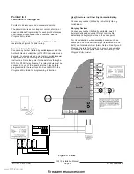
Phone Jack
To prevent jamming of reports, wire the RJ31X jack before
the in-house phone system to support line seizure. See
Figure 6. Line seizure provides for a temporary interrup-
tion of normal phone usage while the communicator
transmits data.
After installation, confirm that the panel seizes the line,
acquires dial tone, reports correctly to the receiver, and
releases the phone line to the in-house phone system.
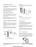
Phone Cord
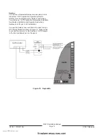
Connect the flying leads of the D160 or D164 Phone Cord
to the panel as shown in Figure 7. Connect the modular
end to the RJ31X.
Power Up
Connect the battery and then plug in the transformer.
Leave the Standby Switch locked down for now.
Program the Panel
Use the Keypad, Radionics D5200 Programmer, or a
remote programmer to program the panel. See the
Program Entry Guide for programming options and
keypad programming instructions.
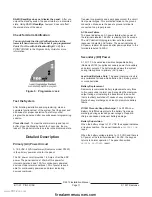
If you’re programming from the keypad or using the
D5200, make sure the Standby Switch is locked down.
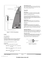
See Figure 8.
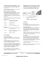
If you’re using the D5200, Figure 9 shows the location of
the programming jack. See the
D5200 Programming
Operation Manual for instructions on using the program-
mer.
Unlock the Standby Switch
When you’re finished programming, move the Standby
Switch to the normal position. See Figure 8. The panel
sends a
RE-BOOT
report to the receiver and returns in the
disarmed state. If you programmed for test reports and left
the hours and minutes to next report prompts at 0 (zero),
the panel sends a test report with the
RE-BOOT
report.
Figure 8: Standby Switch
Figure 7: Phone Cord
Figure 6: RJ31X Phone Jack
(
www.PDF-Zoo.com
firealarmresources.com


