RC16xxxx-SSM
2017 Radiocrafts AS
RC16xxxx-SSM User Manual (rev. 1.00)
Page 4 of 20
Radiocrafts
Embedded Wireless Solutions
SIGFOX protocol
Basic functionality
The SIGFOX protocol defines two types of network modes:
1. Only uplink mode
Packets are only transmitted from the RC16xxxx-SSM module to the base station.
This mode can be used for pure data collection.
2. Uplink and downlink mode
RC16xxxx-SSM does not use this mode
UART Interface for Module Configuration
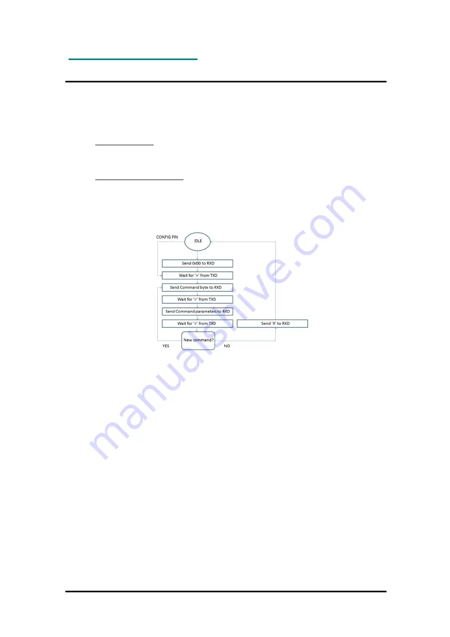
Figure 5: Configuration mode flow diagram
The configuration of the module can be changed in-circuit from the host during operation, at
the time of installation of the equipment, at the manufacturing test, or even as a stand-alone
module. The configuration is changed by sending commands on the UART interface after the
module is set in configuration mode. The configuration mode is entered by sending 00h to the
module (see timing details later), or by asserting the CONFIG pin (set low).
In configuration
mode the module will respond by sending a ‘>’ prompt on the TXD pin. This
indicates that the module is ready to receive commands. The CONFIG pin (if used) can then
be de-asserted. Note that the CONFIG pin must be de-asserted
before
the Exit command (‘X’)
is sent to the module in order to return to normal operation.
After a command is executed, the module responds with the ‘>’ prompt character again,
indicating it is ready for a new command. Do not send a new command
before the ‘>’ prompt
is received. The time required to execute a command can vary depending on the command
(see the Timing Information section). There is no ‘>’ prompt after the ‘X’ exit command.
Permanent changes of parameters can be done by writing to the configuration memory using
the memory command ‘M’. Also, special configurations, such as sensor configuration
(command ‘J’), writing of ID, KEY and PAC (command ‘A’) permanently changes the non-
volatile memory and these changes are remembered across resets and power cycles. See the
Configuration Memory section for details.


