910198 – Tie Tamper
Phone: (262) 637-9681
11.2019 Rev 1.1
Page
12
of
21
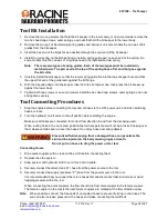
Tool Bit Installation
1. Remove the two cap screws that hold the bit keeper to the lower body or on some models remove the
two hex head cap screws, outer springs, and nuts that hold the bit keeper to the lower body.
2. Remove the two pair of bit-retaining spring guides and spring or on some models the one pair of bit
guides from the bit keeper.
3. Insert the hex end of the bit as far as possible through the small end of the bit keeper.
4. Install the coil spring on the bit hex flange. Install a spring guide pair on each end of the spring. On
some models only the one pair of bit guides need to be installed and
no
spring.
Note: There are two types of spring guides. Each of the two types must be installed in
matched pairs. The pair used at the top of the spring have a flat end that goes against
the bit collar
.
5. Carefully install the bit keeper so that the lower spring guide fits into the lower keeper bore and that
the upper flat end of the guide rests against the bit flange.
6. With the bit pulled down into the keeper, insert into the tie tamper hex, then press the bit keeper up
against the lower body.
7. Tighten both caps crews or on some models install the hex head cap screws, outer springs, and nuts
and tighten securely.
Tool Connecting Procedures
1. Stop the engine before connecting the tool and or hoses to the OFF power unit, and when switching
hoses or tools.
2. Turn the hydraulic on/off valve to the off position before starting the engine.
Make sure all hoses are connected for correct flow direction to and from the tool being used.
When routing hose in the work area, position them where personnel will not be at risk of tripping over
them where vehicles can run over the hoses. Do not lay hose over sharp objects.
Pressurized fluid escaping from a damaged hose can penetrate the
skin and be injected in the body causing injury or death.
Do not pull on hoses to drag the power unit or tool
.
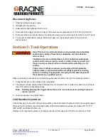
Connecting Hoses
1. Wipe quick couplers with a clean lint free cloth before connecting them.
2. Depressurize the system.
3. Allow system and hydraulic fluid to cool if too hot to handle.
4. Securely connect the return (tank “R”) hose from the power source to the tool.
5. Securely connect the supply (pressure “P”) hose from the power source to the tool.
It is recommended that you connect the return hoses first and disconnect last to minimize or avoid
trapping pressure within the tool.
When connecting the quick couplers, the flow should run from male coupler to the female coupler.
The female coupler on the tool is the inlet. Quick couplers are marked with a flow direction arrow.
Note
: When possible, connect the free ends of uncoupled hoses to prevent build up in the hoses. The
sun can also increase pressure in the hoses and make connecting them difficult.


