Section V - Servicing
Prior to installation, test the separator
element as follows:
) Locate a continuity test light or a
volt-ohm-meter (v-o-m) capable of
reading 20 ohms.
2) Assure that the battery has proper
charge. Touch the probe leads
together to assure the light works or
to zero calibrate the meter.
3) Contact the grounding staple (on
the separator element gasket) or
grounding spring clip (on separator
elements that do not require a
gasket) with the ground probe of the
test indicator.
4) Touch the top cap of the separator
element with the other probe. The
indicator light should illuminate on
the test or the v-o-m test must read
no more than 20 ohms.
5) Touch the bottom cap of the
separator element. The indicator
light should illuminate on the test or
the v-o-m test must read no more
than 20 ohms.
6) Touch the outside wire mesh. The
indicator light should illuminate on
the test or the v-o-m test must read
no more than 20 ohms.
7) Touch the inside wire mesh ( do not
puncture the element media). The
indicator light should illuminate on
the test or the v-o-m test must read
no more than 20 ohms.
8) If the separator element has a gasket
on each side of the flange, repeat
steps 3 through 7.
9) If the separator element fails any
of the above test , return it to your
Quincy Distributor for replacement.
0) Make sure the compressor is
bonded (wired) to an earth ground to
dissipate static electricity.
Added QGV-50/200 Separator Installation. (0/0/07)
QGV-150/200 Separator Installation
The 50 and 200 horsepower models
utilize an inside/out flow requiring the
separator seal to be located on the inlet
to the separator. The sealing surface is
located inside the pressure vessel and
is coated to prevent corrosion. Remove
any loose material prior to separator
installation.
After the continuity verification procedure
is complete install the separator as follows:
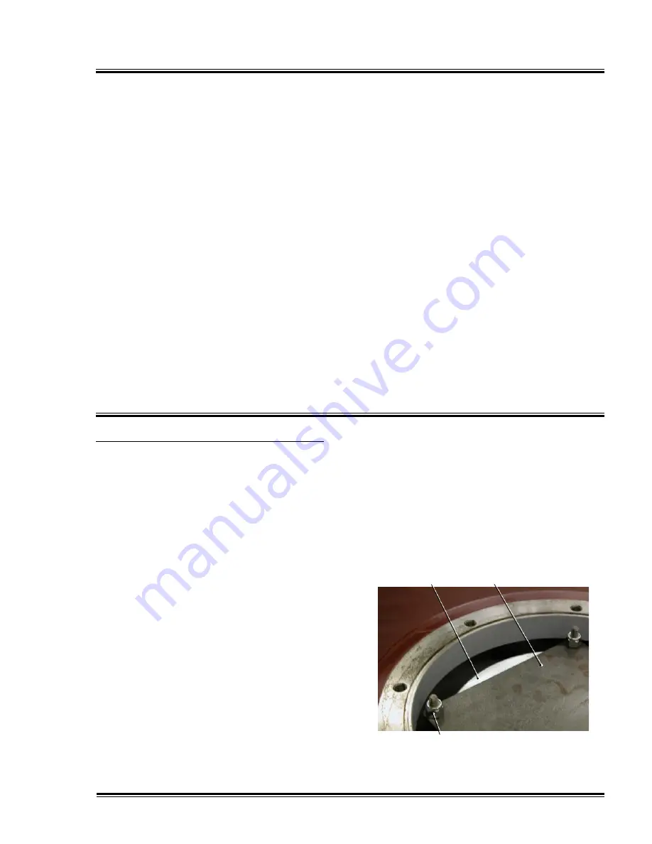
. Lubricate the separator o-ring with
compressor fluid and place separator
inside the reservoir with o-ring end
facing down, centered inside studs.
2. Place the square separator
compression plate over the 4 studs.
3. Install the (4) Nylok nuts on studs and
tighten as follows:
Turn nuts down until they’re touching
the compression plate.
Do not
overcompress o-ring.
Tighten nuts by turning clockwise
½ turn in a cross pattern. Over
tightening the compression plate
will deform the separator, reducing
performance.
separator
retaining
plate
threaded
rod
&
nylok
nut
Quincy Compressor-QGV Series
39
Содержание QGV Series
Страница 2: ......
Страница 6: ......
Страница 17: ...Section II Description This page intentionally left blank Quincy Compressor QGV Series 11...
Страница 74: ...Appendix A Dimensional Drawings QGV 50 air cooled 68 Quincy Compressor QGV Series...
Страница 75: ...Appendix A Dimensional Drawings QGV 50 water cooled Quincy Compressor QGV Series 69...
Страница 76: ...Appendix A Dimensional Drawings QGV 75 100 air cooled 70 Quincy Compressor QGV Series...
Страница 77: ...Appendix A Dimensional Drawings QGV 75 100 water cooled Quincy Compressor QGV Series 71...
Страница 78: ...Appendix A Dimensional Drawings QGV 150 200 air cooled 72 Quincy Compressor QGV Series...
Страница 79: ...Appendix A Dimensional Drawings QGV 150 200 water cooled Quincy Compressor QGV Series 73...
Страница 89: ......


