background image

1

2

3

4

5

6

7

56

5 m

m

1

4

7

m

m

106

mm

155

mm

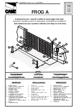
DIMENSIONS

VIEW OF TYPICAL AUTOMATION AND NAMES OF COMPONENTS

1.

FIXING PLATE OF

THE MOTOR

2.

MOTOR

3.

ARMS KIT

4.

SAFETY EDGE

5.

PHOTOCELLS

6.

FLASHING LIGHT
+ ANTENNA

7.

CONTROL BOARD
(IF NOT INCLUDED IN

THE MOTOR)

CONSIDERATIONS FOR INSTALLATION

Ÿ

 The installation and testing operations must be performed only by qualified


personnel in order to ensure the proper and safe operation of the automated door.

Ÿ

The manufacturer declines all responsibility for damages caused by incorrect
installations due to incompetence and/or negligence.
Before installing the automation, check that the door is perfectly working and
balanced.

Note: The increase of counterweights is equal to the weight of the frame that
you will install on the door in addition to the weight of the motor

.

Содержание BOXTER QK-B24

Страница 1: ...GEARMOTOR FOR GARAGE DOORS WARNING Before installing thoroughly read this manual that is an integral part of the pack BOXTER USER MANUAL V03 2016 ENG...

Страница 2: ...upply 230Vac 24Vdc Motor power 250 W 50W Motor rpm 1400 1800 Capacitor 12 5 F Average power consumption 1 3 A 3 A Mechanical release for emergency operation Indoor use with possibility of outdoor use...

Страница 3: ...d testing operations must be performed only by qualified personnel in order to ensure the proper and safe operation of the automated door The manufacturer declines all responsibility for damages cause...

Страница 4: ...sting arm of the door Make sure there are at least 20 mm of space between the door frame and the box of the counterweights Note If you are not able to use the straight telescopic arm use the curved on...

Страница 5: ...he transmission tube to the straight or curved arm M 50 100 mm 50 100 mm Straight or curved arm Place and securely fix the tube support to the door frame at a distance between 50 and 100 mm downwards...

Страница 6: ...F THE LATERAL FIXING PLATES LIMIT SWITCH ADJUSTMENT Close the door Place the limit switch C in order to touch the lever of the microswitch of the closing limit switch and tigthen the screw Open the do...

Страница 7: ...TOMATION WITH NON PROJECTING DOOR Place and securely fix the tube support to the door frame at a distance of 110 mm under the center of the door look at fig 7 8 The rotation axis of the motor must be...

Страница 8: ...am is interrupted Check the connection remove any obstacle across the beam On giving a command with the remote control the door doesn t open but works with the key command The remote control has not b...

Страница 9: ...ts of the regulations Electromagnetic Compatibility Directive 2004 108 EC Low Voltage Directive 2006 95 EC Machinery Directive 2006 42 EC and their amendments and modifications and with the regulation...

Страница 10: ...ific national technical regulations have been followed EN 12453 EN 12445 on Industrial Commercial and Residential Gates and Doors Safe Use of Motorized Doors Requirements and Classification Test Metho...

Страница 11: ...on are not comlplied with ATTENTION il vous pla t attentivement ce manuell installation QUIKO d cline toute responsabilit cas de non conformit ces glements Apparecchiatura di comando 1 Motore 230Vac C...

Страница 12: ...C COM N C 1 2 3 4 5 6 7 8 9 10 11 12 13 14 15 16 17 18 19 20 COM Start Stop 2 1 7 6 Example wiring selector CONTACT NO CONTACT NC 1 2 3 4 ON PROG RADIO PED START ANT STOP LSC 24Vac M LSO STOP LSC LSO...

Страница 13: ...stop at close limitswitch if you chose an automatism without limitswitches must give a further impulse to fix the stopping point of the stroke If you choose to have the AUTOMATIC CLOSING OPTION 2 IN...

Страница 14: ......

Страница 15: ......

Страница 16: ...Quiko Italy Via Seccalegno 19 36040 Sossano VI Italy Tel 39 0444 785513 Fax 39 0444 782371 info quiko biz www quikoitaly com...

Отзывы: