REV 001
A
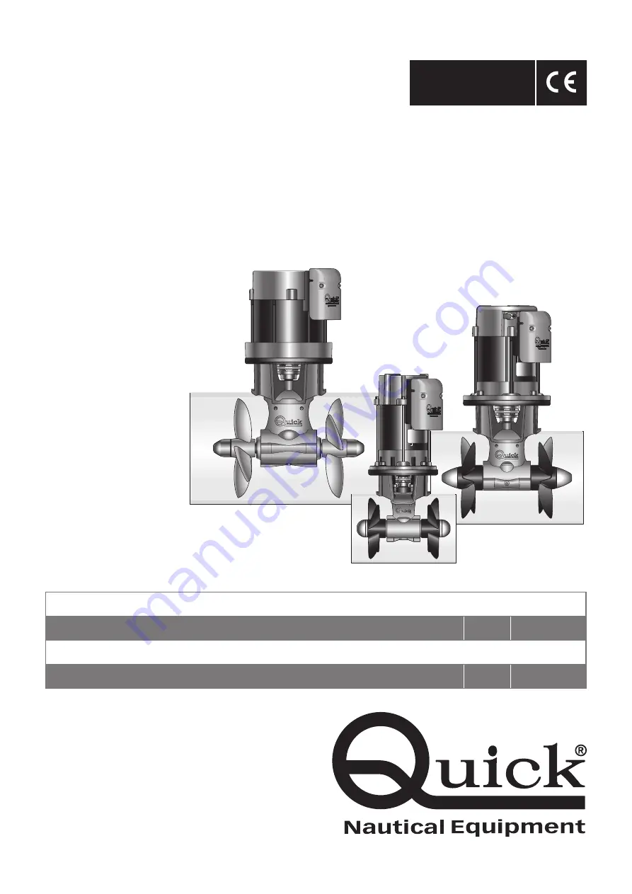
ELICHE DI MANOVRA DI PRUA
MANUALE D'INSTALLAZIONE E USO
IT
pag. 3
BOW THRUSTERS
INSTALLATION AND USE MANUAL
EN
page 17
BT
DC-AC
DOUBLE PROPELLER
BT DC-AC185BT DC-AC250BT DC-AC300
Страница 1: ...REV 001A ELICHE DI MANOVRA DI PRUA MANUALE D INSTALLAZIONE E USO IT pag 3 BOW THRUSTERS INSTALLATION AND USE MANUAL EN page 17 BTDC AC DOUBLE PROPELLER BT DC AC185 BT DC AC250 BT DC AC300 ...
Страница 2: ......
Страница 3: ...5 3 Sicurezza Pag 5 3 0 Avvertenze Pag 5 4 lnstallazione Pag 6 4 0 Requisiti per l installazione Pag 6 4 1 Il tunnel Pag 6 4 2 Il thruster Pag 8 4 3 Il piede e la flangia di supporto motore Pag 9 4 4 Montaggio delle eliche Pag 9 4 5 Ambiente di installazione del controller Pag 10 4 6 Montaggio del controller Pag 10 5 Schema di collegamento Pag 11 5 0 Sistema base DC AC185 250 300 Pag 11 6 Avverten...
Страница 4: ...e competente e di consultare il costruttore o gli architetti navali per valutare appieno l entità dei lavori PRIMA DI UTILIZZARE L ELICA DI MANOVRA LEGGERE ATTENTAMENTE IL PRESENTE MANUALE D USO IN CASO DI DUBBI CONSULTARE IL RIVENDITORE QUICK QUICK SI RISERVA IL DIRITTO DI APPORTARE MODIFICHE ALLE CARATTERISTICHE TECNICHE DELL APPARECCHIO E AL CONTENUTO DI QUESTO MANUALE SENZA ALCUN PREAVVISO F M...
Страница 5: ... Chiave a forchetta da 27 mm 3 Sicurezza 3 0 Avvertenze I thruster Quick sono stati progettati e realizzati per asservire all uso nautico Non utilizzare questi apparecchi per altri tipi di applicazioni Quick non si assume alcuna responsabilità per i danni diretti o indiretti causati da un uso improprio dell apparec chio o da una scorretta installazione Il thruster non è progettato per mantenere ca...
Страница 6: ...enomeni di cavitazione nell elica si dovrà posizionare il tunnel più a fondo possi bile L effetto di leva nell imbarcazione è proporzio nale all aumento della distanza L1 e L2 che si rileva tra il baricentro e la posizione del tunnel A e B L aumento della lunghezza del tunnel aumenta l effetto delle perdite di carico diminuendo la forza nominale di propulsione Per limitare le perdite di carico la ...
Страница 7: ...scafo dell imbarcazione o in alternativa realizzare un deflettore nella parte anteriore del tunnel Nel caso in cui il tunnel sia vicino alla linea di galleggiamento è consigliabile prevedere l inseri mento di una grata all estremità del tubo La grata deve avere maglie verticali e più larghe possibili per non contrastare la spinta dell elica Le maglie verticali impediscono l ingresso della maggior ...
Страница 8: ...i contatto fra la flangia e il tubo ciò potrebbe cau sare disallineamenti E necessario asportare con carta vetrata eventuali residui di resina e di tutti gli eventuali impedimenti al corretto contatto Il thruster può essere installato con qualunque angolo all interno di 90º dalla verticale Se il motore elettrico è posizionato per necessità con un angolo superiore a 30º rispetto alla verticale si r...
Страница 9: ...enuta Come ulteriore precauzione contro l ingresso d acqua applicare silicone per uso nautico nella zona di contatto tra flangia e tubo Fissare il tutto con la flangia utilizzando le specifiche viti e rondelle 4 3 Il piede riduttore e la flangia di supporto motore 4 4 Le eliche ATTENZIONE accertarsi ad assemblaggio ultimato che l elica sia ben centrata all interno del tunnel SILICONE Montaggio del...
Страница 10: ...inali elettrici Un serraggio non corretto può provocare un sur riscaldamento pericoloso del fusibile e del portafusibile ATTENZIONE alcuni componenti possono raggiungere temperature elevate pericolo di ustione Lasciare raffreddare prima di maneggiarlo ATTENZIONE prima di collegare o scollegare il fusibile o i cavi dai terminali elettrici accertarsi che i cavi non siano sotto tensione Installazione...
Страница 11: ...BT DC AC185 250 300 5 Schema di collegamento B B B B U V W V W U MOTORE ELICA DI MANOVRA BATTERIA FUSIBILE RAPIDO 4A INTERRUTTORE COMANDO AJ1 THRUSTER TELERUTTORE DI LINEA BLU GRIGIO ROSSO PROLUNGA CAVO CONTROLLER AC MOTOR CONTROLLER 5 0 Sistema base BT DC AC 185 250 300 ...
Страница 12: ...ti galleggianti nelle vicinanze prima di avviare l elica Non deve essere presente materiale infiammabile nel gavone o nella zona in cui sia presente il motore del Thruster Non utilizzare il bow thruster fuori dall acqua per un tempo superiore a 10 secondi Durante l ormeggio si raccomanda di non lasciare cime libere in acqua che potrebbero essere risucchiate dalle eli che causandone la rottura 6 0 ...
Страница 13: ...13 Sostituire gli anodi di zinco 18 effettuare più frequen temente se necessario Sostituire le eliche se danneggiate o usurate Controllare il serraggio di tutte le viti Accertarsi che non vi siano infiltrazioni di acqua all in terno Verificare che tutte le connessioni elettriche siano ben fissate e prive di ossido Verificare che le batterie siano in buone condizioni ATTENZIONE non verniciare gli a...
Страница 14: ...P KIT FLANGIA PER ELICA BTQ300 FVSGFLBTQ300A00 3 OSP KIT RIDUTTORE BTQ185 DP FVSGGBBT185DA00 OSP KIT RIDUTTORE BTQ250 DP FVSGGBBT2500A00 OSP KIT RIDUTTORE BTQ300 FVSGGBBT3000A00 4 OSP KIT ELICA D185 RH FVSGEL185R00A00 OSP KIT ELICA D250 RH FVSGEL250R00A00 OSP KIT ELICA D300 RH NIBRAL FVSGEL300RN0A00 5 OSP KIT ELICA D185 LH FVSGEL185L00A00 OSP KIT ELICA D250 LH FVSGEL250L00A00 OSP KIT ELICA D300 LH...
Страница 15: ... BT DC AC185 250 300 10 Dimensioni eliche di manovra max Ø 198 7 51 64 Ø 185 7 9 32 265 10 7 16 345 13 37 64 max Ø 272 10 45 64 361 14 7 32 Ø 250 9 27 32 373 14 11 16 BT DC AC 185 105 BT DC AC 250 140 BT DC AC 300 300 361 14 7 32 Ø 319 12 9 16 Ø 300 11 13 16 434 17 3 32 ...
Страница 16: ......
Страница 17: ...installation Pag 19 3 Safety Pag 19 3 0 Warnings Pag 19 4 Installation Pag 20 4 0 Thruster positioning Pag 20 4 1 The tunnel Pag 20 4 2 The thruster Pag 22 4 3 Gearleg and motor support flange Pag 23 4 4 Propeller fitting Pag 23 4 5 Controller installation site Pag 24 4 6 Controller installation Pag 24 5 Connection diagram Pag 25 5 0 Basic system DC AC185 250 300 Pag 25 6 Warnings Pag 26 6 0 Warni...
Страница 18: ...rchitects to fully evaluate the entity of the work BEFORE USING THE THRUSTER CAREFULLY READ THIS USER MANUAL IF IN DOUBT CONTACT YOUR NEAREST QUICK DEALER QUICK RESERVES THE RIGHT TO INTRODUCE CHANGES TO THE EQUIPMENT AND THE CONTENTS OF THIS MANUAL WITHOUT PRIOR NOTICE IN CASE OF DISCREPANCIES OR ERRORS BETWEEN THE TRANSLATED TEXT AND THE ORIGINAL ITALIAN TEXT PLEASE REFER TO THE ITALIAN TEXT F 1...
Страница 19: ...arnings Quick Thrusters have been designed and constructed only for nautical use Do not use these appliances for other uses Quick shall accept no responsibility for direct or indirect damages caused by improper use of the appliance or an im proper installation The Thruster is not designed to maintain loads generated in particular atmospheric conditions storms We recommend you entrust preparation a...
Страница 20: ... waterline To avoid cavitation in the propeller the tunnel must be positioned as low as possible The lever effect in the boat is proportional to the increase of the distance L1 and L2 between the barycentre and the position of the tunnel A and B An increase in the length of the tunnel increases the effect of the loss of charge decreasing the nominal driving force To limit losing charge the optimal...
Страница 21: ...e rear part of the tunnel Otherwise create a deflector on the front part of the tunnel If the tunnel is near the waterline it is advisable to fit a grating at the end of the tube The grating must have as large a vertical mesh as possible to avoid contrasting the propeller thrust The vertical mesh prevents the entry of most of the floating objects The rounded ends of the tunnel limit the creation o...
Страница 22: ...Take care that there are no resin residues in the contact area between flange and tube this could cause misalignment Any resin residues and any other hindrance to correct contact must be removed by sandpaper The thruster can be installed at any angle within 90 from vertical If the electric motor is positioned of necessity at an an gle of more than 30 from vertical a special support must be constru...
Страница 23: ...nst the entry of water apply silicone for nautical use around the point of contact be tween flange and tube Fasten everything to the flange using the special screws and washers 4 3 Gearleg and motor support flange 4 4 The propellers WARNING on conclusion of assembly make sure that the propeller is exactly positioned at the central point of the tunnel SILICONE Propellers fitting Insert the drive pi...
Страница 24: ... properly tighten the bolts of the electrical terminals Otherwise dangerous overheating of both fuse and fuseholder may occur WARNING some components may reach high temperatures burn hazard Leave the fuseholder to cool off before handling it WARNING before connecting or disconnecting fuses or wires from the electrical terminals make sure that the wires are not live Suitable installation only verti...
Страница 25: ...L IT EN REV001A BT DC AC185 250 300 5 Connection diagram 5 0 Basic System BT DC AC 185 250 300 B B B B U V W V W U MOTOR THRUSTER BATTERY 4A FAST FUSE SWITCH AJ1 THRUSTER COMMAND LINE CONTACTOR BLUE GREY RED EXTENSION CONTROLLER CABLE AC MOTOR CONTROLLER ...
Страница 26: ...loating objects are in the vicinity before switching on the thruster There must not be flammable materials in the peak or in the area where the Thruster motor is Do not operate the bow thruster out of the water for more than 10 seconds During mooring it is recommended not to leave in the water any free line which may be sucked in by the propel lers thus leading them to break 6 0 Warnings 7 0 Use o...
Страница 27: ...an propellers 15 and 16 tunnel and gearleg 13 Replace the zinc anodes 18 carry out this operation more often if needed Replace the propellers if damaged or worn out Check the tightness of all screws Ensure that there is no water seepage inside Check that all electrical connections are well tightened and oxide less Check that the batteries are in good conditions WARNING do not paint the anodes 18 t...
Страница 28: ...0 OSP BTQ300 FLANGE FOR PROPELLER KIT FVSGFLBTQ300A00 3 OSP BTQ185 DP GEARLEG KIT FVSGGBBT185DA00 OSP BTQ250 DP GEARLEG KIT FVSGGBBT2500A00 OSP BTQ300 DP GEARLEG KIT FVSGGBBT3000A00 4 OSP KIT PROPELLER D185 RH FVSGEL185R00A00 OSP KIT PROPELLER D250 RH FVSGEL250R00A00 OSP KIT PROPELLER D300 RH NIBRAL FVSGEL300RN0A00 5 OSP KIT PROPELLER D185 LH FVSGEL185L00A00 OSP KIT PROPELLER D250 LH FVSGEL250L00A...
Страница 29: ...001A BT DC AC185 250 300 10 Thruster dimensions max Ø 198 7 51 64 Ø 185 7 9 32 265 10 7 16 345 13 37 64 max Ø 272 10 45 64 361 14 7 32 Ø 250 9 27 32 373 14 11 16 BT DC AC 185 105 BT DC AC 250 140 BT DC AC 300 300 361 14 7 32 Ø 319 12 9 16 Ø 300 11 13 16 434 17 3 32 ...
Страница 30: ...NOTES ...
Страница 31: ......
Страница 32: ...el 39 0544 415061 Fax 39 0544 415047 www quickitaly com quick quickitaly com REV 001A MANUALE D INSTALLAZIONE ED USO INSTALLATION AND USE MANUAL Codice di serie del prodotto Product code and serial number BTDC AC DOUBLE PROPELLERS BT DC AC185 BT DC AC250 BT DC AC300 ...