


M20 Hardware Design
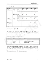
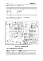
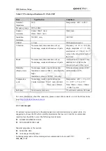
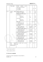
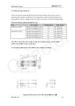
Table 27: Product specifications of U.FL-R-SMT
Item
Specification
Condition
Nominal
impedance
50
Ω
. Temperature:
-40
℃
to 90
℃
Frequency range
DC to 6GHz.
Contact
resistance
Center: 20m
Ω
max.
Outer: 10m
Ω
max.
10mA max.
Insulation
resistance
500 M
Ω
min.
100V DC
VSWR
1.5 max
With mated connector
Vibration
No momentary disconnections of 1
μ
s;
No damage, cracks and looseness of parts
Frequency of 10 to 100 Hz,
single amplitude of 1.5 mm,
acceleration of 59m/s2, for 5
cycles in the direction of each of
the 3 axes
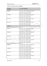
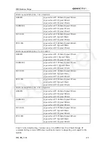
Shock
No momentary disconnections of 1
μ
s;
No damage, cracks and looseness of parts
Acceleration of 735m/s2, 11ms
duration for 6 cycles in the
direction of each of the 3 axes
Humidity
(Steady state)
No damage, cracks or parts dislocation.
Insulation resistance 10M
Ω
min.(humidity
high)
Insulation resistance 500M
Ω
min.(dry)
96 hours at temperature of 40
℃
and humidity of 95%
Temperature
cycle
No damage, cracks or parts dislocation.
Contact resistance: 25m
Ω
max. (Center)
15m
Ω
max. (Outer)
Temperature: -40
℃→
+5 to +35
℃→
+90
℃→
+5 to +35
℃
Time: 30min.
→
3min.
→
30min.
→
3min. 5 cycles
Salt spray
No excessive corrosion
5% salt water solution, 48 hours
For more information about the connector, please contact Hirose dealer or visit the Hirose home
page
http://ww.hirose-connectors.com
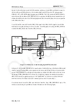
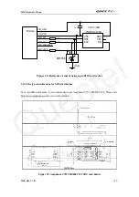
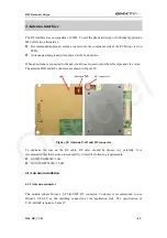
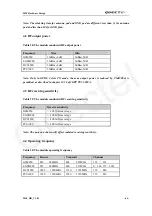
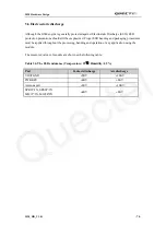
4.1.2 Antenna pad
If customer connects antenna to the antenna pad via a soldered microwave coaxial cable, it is
suggested to choose the RF cable carefully to minimize the loss on it. And the recommended
insertion loss should try to meet the following requirements:
z
GSM850/EGSM900<0.5dB
z
DCS1800/PCS1900<1dB
Material properties of the module:
z
M20 PCB: FR4
z
Antenna pad: Gold plated
Soldering temperature of the antenna pad is recommended to be around 350 .
℃
M20_HD_V1.01
- 63 -
Quectel


