5G Module Series
5G-M2_EVB_User_Guide 16 / 34
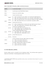
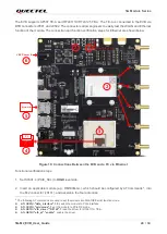
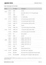
Table 5: Description of Switches, Button and Status Indicators
3.3. M.2 Interface (J0101)
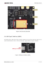
The M.2 interface (J0101) is designed to mount applicable modules. This interface allows engineers to
easily test functionalities or develop applications based on the module.
1
Pin definitions might be different among applicable modules, please contact Quectel Technical Support in case of a
different pin definition.
RefDes
Function Description
S0201
Used to power on/off the EVB and module
S0101
Used to turn on/off the module
S0102
Used to reset the module
S0301
S0301.1
⚫
LOW:
the module’s Pin 38 and 68
1
are connected to J0803 SLIC TE-A
⚫
HIGH:
the module’s Pin 38 and 68
are connected to J0803 CODEC TE-A
S0301.2
⚫
LOW:
the module’s Pin 20, 22, 24, and 28 are connected to J0501 and J0502
⚫
HIGH: the modul
e’s Pin 20, 22, 24, and 28 are connected to J0803
S0301.3
Quectel internal use only
S0301.4
⚫
LOW:
the module’s PCIe is connected to J0401 USB Type-B Connector
⚫
HIGH:
the module’s PCIe is connected to J0501 and J0502
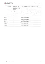
S1101
S1101.1
Used to turn on/off airplane mode
⚫
LOW (FLIGHT_MD): turn on airplane mode
⚫
HIGH (NORMAL_MD): turn off airplane mode
S1101.2
Used to enable/disable GNSS function
⚫
LOW (GNSS_OFF): disable GNSS function
⚫
HIGH (GNSS_ON): enable GNSS function
S1101.3
Quectel internal use only
S1101.4
Reserved
D0107
Power on/off status indicator (PWR_LED) for the module
⚫
Light on: the module is powered on
⚫
Light off: the module is powered off
D0108
RF status indicator (WWAN_LED) for the module
⚫
Light on: RF function is enabled
⚫
Light off: RF function is disabled


