Queclink GV300CAU Series Скачать руководство пользователя страница 9

GV300CAU

 Series User Manual 

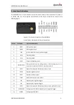
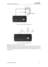
3. Interface Definition

The 

GV300CAU

 has a 16-pin interface connector which contains the connections for power, I/

O,  RS232,  MIC,  etc.  The  sequence  and  definition  of  the  16-pin  connector  are  shown  in  the 
following figure: 

Figure 3.


The 16-pin Connector on the 

GV300CAU


Series Table 6.


Description of 16-pin Connections 

Pin No.  Pin Name 

Function Description 

MICP 

MIC positive input 

MICN 

MIC negative input 

IGN 

Ignition detection input, positive trigger 

RXD 

The RXD_RS232 

TXD 

The TXD_RS232 

GND 

Power and digital ground 

ADIN3/OUT3 

One special I/O can be configured as a 0-32V analog input or an 
open drain output with 150 mA max drive current 

OUT2 

Open drain output2, 150mA max drive current 

SPKN 

Speaker negative output 

10 

SPKP 

Speaker positive output 

11 

PWR 

External DC power input, 8-32V 

12 

IN2 

Digital input2, negative trigger 

13 

IN1 

Digital input1, negative trigger 

14 

OUT1 

Open drain output1, 150mA max drive current, with latch circuit 

15 

ADIN1/IN3 

Analog input1 (0-32V) or digital input 3, negative trigger 

16 

ADIN2 

Analog input2 (0-32V) 

QSZTRACGV300CUM0101  

 6 

Содержание GV300CAU Series

Страница 1: ...GV300CAU Series User Manual GV300CAU Series User Manual GSM GPRS WCDMA LTE Cat1 GNSS Tracker QSZTRACGV300CUM0101 Version 1 01...

Страница 2: ...n Furthermore system validation of this product designed by Queclink within a larger electronic system remains the responsibility of the customer or the customer s system integrator All specifications...

Страница 3: ...ng and Closing the Case 9 5 2 Installing a SIM Card 9 5 3 Installing the Internal Backup Battery 10 5 4 Switching on the Backup Battery 10 5 5 Installation of the External GPS Antenna Optional 10 5 6...

Страница 4: ...CAU Series User Manual 0 Revision History Version Date Author Description of Change 1 00 2020 06 20 Arry Wang Initial 1 01 2020 09 02 Arry Wang Modify interface definition description QSZTRACGV300CUM0...

Страница 5: ...ntegration is straightforward as complete documentation is provided for the full featured Track protocol The Track protocol supports a wide variety of reports including emergency alarm Geo fence bound...

Страница 6: ...th could be Master and Slave When the device role is Slave the device will provide below services device information service battery information service virtual serial port service Other devices can r...

Страница 7: ...arching GPS signal Fast flashing GPS chip has received GPS signal ON Upgrading the device firmware over the air Fast flashing PWR Note 2 No external power and internal battery voltage is not lower tha...

Страница 8: ...If anything is missing please contact your supplier Table 5 GV300CAU Series Parts List Name Picture Description GV300CAU Locator 80 49 26 mm GSM GPRS WCDMA LTE Cat1 GNSS tracker User Cable GV300CAU Se...

Страница 9: ...ection input positive trigger 4 RXD The RXD_RS232 5 TXD The TXD_RS232 6 GND Power and digital ground 7 ADIN3 OUT3 One special I O can be configured as a 0 32V analog input or an open drain output with...

Страница 10: ...tion Color PIN No Cable PIN No Color Definition OUT2 Yellow 8 16 Brown White ADIN2 ADIN3 OUT3 Brown 7 15 Green ADIN1 IN3 GND Black 6 14 Blue OUT1 TXD White Black 5 13 Orange IN1 RXD Pink 4 12 Orange B...

Страница 11: ...To close Place the cover on the bottom at the position as shown above Slide the cover against the direction of the arrow until it snaps 5 2 Installing a SIM Card Install the SIM card into the holder w...

Страница 12: ...h and ON OFF Position Note 1 The switch must beat the OFF position when the GV300CAU series is shipped on an aircraft 2 When the switch is at the OFF position the battery cannot be charged nor be disc...

Страница 13: ...o find a non permanent power source that is only available when the vehicle is running for example the power source for the FM radio IGN signal can be configured to transmit information to the backend...

Страница 14: ...max drive current Figure 12 Analog Input or Digital out Connection 5 10 Digital Outputs There are three digital outputs on GV300CAU All are of open drain e type and the maximum drain current is 150 m...

Страница 15: ...state during reset Warning Many modern relays come with a flyback diode pre installed internal to the relay itself If the relay has this diode insure the relay polarity connected is properly used If t...

Страница 16: ...ies User Manual 5 11 Serial Port UART Interface There are two lines dedicated to the Serial Port UART interface TXD RXD TXD RXD is standard RS232 signal Figure 16 Connection with RS232 Port QSZTRACGV3...

Страница 17: ...he device to a reliable surface to prevent falling off Make the side with antenna face sky to have better signal reception Do not install the device under metal surface or in enclosed environments hav...

Страница 18: ...dress for the backend server is an identified address in the internet There is no response from UART when the device is configured by using UART The port is not ready or the device is not powered on P...

Страница 19: ...8 Appendix Supported Accessories DATA_CABLE_M 1 Wire temperature sensor Relay with socket RS232 Camera Antenna_GPS_SMA_3M UFS300 Garmin RFID reader DR102 DUT E RF 433MHz accessories WRT100 WTH100 WTS...

Страница 20: ...ence by one or more of the following measures Reorient or relocate the receiving antenna Increase the separation between the equipment and receiver Connect the equipment into an outlet on a circuit di...

Отзывы: