TIMTER
™ Multi
-mode Dual
Telemetry Transmitter
24
Quasonix, Inc.
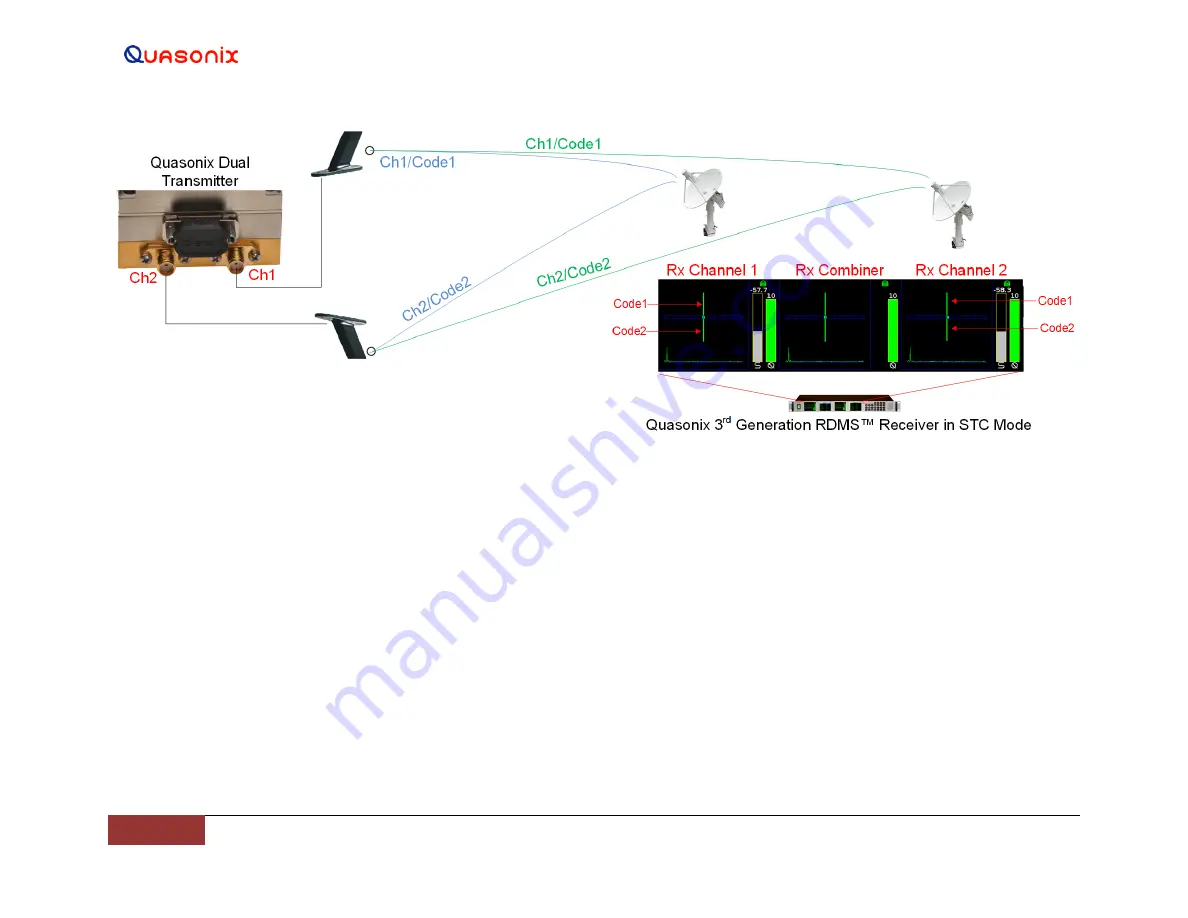
Figure 22: Dual Transmitter RF Outputs Connected to Upper and Lower Antenna Transmitting to Receiver in STC Mode
Explanation of Dual Transmitter to RDMS Receiver Example
The signals from the two transmitter RF connectors are transmitted simultaneously. The signals from the upper (Ch1) and lower (Ch2) antennas are received at
the ground antenna(s) providing input to the receiver. STC consists of the sum of the two unsynchronized phase modulated signals with seemingly unrelated data
that must be recombined to recover the original source data.
Since no traditional constellation exists for this mode, the receiver displays the relative strength of each signal, the difference in time of arrival between them,
and the received strength of the embedded pilot sequences. In this example, one of the signals is transmitted out the top antenna of a vehicle while the other
signal is transmitted from the bottom. In this setup, the height of the green line above the blue graduated horizontal bar represents the relative strength of the top
antenna, while the length of the green line below the bar represents the strength of the bottom. The small green square within the blue bar represents the time
difference of arrival in increments of ¼ of a bit period with all the way to the left or right representing a full bit period.
For information about bench set up for STC and LDPC, refer to Appendix B
Bench Set Up for STC and LDPC.


