Topaz 8 Plus
Alter
Micro Low Air Loss Pressure Relief System
User Manual
Manufactured by:
Air Kinetic Technologies Corp.
Distributed by: Quart Healthcare Inc.
36 Northline Road, Unit 9
Toronto, ON
M4B 3E2
www.quarthealthcare.com
Страница 1: ...Alternating Micro Low Air Loss Pressure Relief System User Manual Manufactured by Air Kinetic Technologies Corp Distributed by Quart Healthcare Inc 36 Northline Road Unit 9 Toronto ON M4B 3E2 www quarthealthcare com ...
Страница 2: ...Please do not power off or unplug the Control Unit while in operation 2 Always use the same voltage as stated on the label Do not use other power cords on the Control Unit 3 Equipment is not suitable to use in the presence of a flammable anesthetic mixture with air or with oxygen or nitrous oxide 4 Keep away from sharp objects 5 Close supervision is necessary when this product is used by on or nea...
Страница 3: ...3 Remove all electro magnetic or RF generated equipment from close proximity to avoid electromagnetic interference 14 The Control Unit will have minor heat generated in operation avoid prolonged contact 15 When the main power supply is lost or has failed temporarily the Control Unit will stop working and the power failure alarm will sound for up to 20 minutes This is normal and the product will re...
Страница 4: ...NUAL BEFORE USE KEEP AWAY FROM FLAMMABLE MATERIALS IP21 WATER AND DUST PROTECTION CLASSIFICATION FUSE SPECIFICATION DISPOSAL OF ELECTRICAL ELECTRONIC EQUIPMENT WEEE THIS PRODUCT SHOULD BE HANDED OVER TO AN APPLICABLE COLLECTION POINT FOR THE RECYCLING OF ELECTRICAL AND ELECTRONIC EQUIPMENT UL CERTIFICATION LOGO COMPLIACE WITH IEC60601 1 WITH RESPECT TO ELECTRICAL SHOCK FIRE AND MECHANICAL HAZARDS ...
Страница 5: ...5 2 INTENDED USE 5 3 PRODUCT DESCRIPTION 5 4 PRODUCT INSTALLATION GUIDE 6 5 PANEL DISPLAY AND OPERATION GUIDE 8 6 CLEANING 13 7 STORAGE 14 8 MAINTENANCE 14 9 DISPOSAL OF AIR MATTRESS 15 10 TROUBLESHOOTING 15 11 TECHNICAL DATA 16 ...
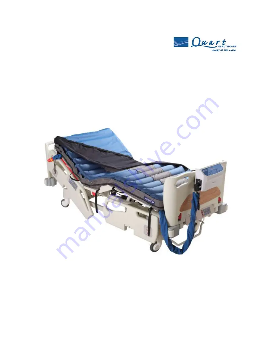
Страница 6: ...oxide 3 PRODUCT DESCRIPTION The Topaz 8 Plus Low Air Loss Mattress System is an alternating mattress replacement system used in the prevention and relief for patients with or vulnerable to pressure wounds The Topaz 8 Plus Low Air Loss Mattress System offers patients a comfortable and relaxing support surface by using the established principles of alternating therapy which can both prevent skin bre...
Страница 7: ...raps or binding side straps 4 Ensure the CPR valve is at CLOSE position before turning on the power 5 Position the Control Unit by its elastic hanger brackets over footboard of the bed The elastic hanger brackets will self adjust onto the footboard tightly 6 Remove the Transport Cap of the hose connector and connect the hose connector to the Control Unit Firmly push the hose connector into positio...
Страница 8: ...oltage CAUTION The Control Unit can only be used with the mattress recommended by the manufacturer Do not use the Control Unit for any other purpose WARNING Do not place the Control Unit in any area where power cord can come off easily 10 For patient transportation press Auto Firm button and wait for 5 minutes for the mattress to be inflated Disconnect the hose from the Control Unit and put on the...
Страница 9: ...nction Mode Selection Alternate Static Constant Low Pressure Panel Lock out Comfort Control Auto Detection 5 1 1 Alarm Mute Press the alarm mute button to temporarily suspend alarms Should the situation not be resolved and fault conditions continue the alarm will resume notifying the patient and caregiver 5 1 2 Alternate Time Display Alternate cycle time can be selected from 10 30 minutes by press...
Страница 10: ...ed cycle time until another mode is selected Static the mattress maintains at the selected pressure The Control Unit will automatically fall back to alternation mode after 20 minutes Constant Low Pressure CLP the mattress maintains at a reduced selected pressure in static mode 5 1 6 Panel Lock Out Press the Lock Out button to lock the panel Should the panel remain untouched for 30 seconds the Lock...
Страница 11: ... then the Control Unit will enter operate mode directly P S To test the alarm battery press to turn off the power and the power failure alarm should be triggered Refer to 5 2 3 Audiovisual Alarm if the alarm is not triggered Press the Operate button and the system will begin to inflate and the Auto Firm indicator will be flashing The mattress should be fully inflated within 60 minutes and automati...
Страница 12: ...e to turn off the system refer 5 2 4 Alarm Mute Table 1 Weight and Comfort Level Reference 5 2 2 CPR When CPR needs to be performed quickly rotate the CPR valve to OPEN position at the same time disconnect the hose connector from the Control Unit to speed up the air release 5 2 3 Audiovisual Alarm Power Failure When electrical shortages occur or power cord is unplugged without turning off the Cont...
Страница 13: ...pressure alarm if the pressure resumes back to normal then the low pressure alarm will stop When more than one alarm is triggered the alarm will be performed according to priority level Refer to Table 2 Warning Code Reference Table for priority level Table 2 Warning Code Reference PRIORITY HIGH LOW WARNING CODE INDICATOR LED AUDIBLE OUTPUT MODE CONDITION OF OUTPUT WARNING DESCRIPTION REMARKS 0 N A...
Страница 14: ...ay from dust If other detergent is used choose one that will have no chemical effects on the surface of the plastics case of the Control Unit CAUTION Do not immerse or soak the Control Unit Clean the mattress cover by using single use wipes with a solution of neutral detergent and hand hot water Rinse thoroughly with clean water and damp dry the mattress using single use wipes Disinfecting the cov...
Страница 15: ...based product for cleaning CAUTION After cleaning dry the mattress without direct exposure of sunlight 7 STORAGE To quickly vacuum air out from mattress for storage rotate the CPR valve to OPEN position and disconnect the hose connector to release the air Lay the mattress out flat and upsides down Roll from the head end towards the foot end Packing strap can then be stretched around the rolled mat...
Страница 16: ...tches with the Control Unit model xxBBB xxx The AAA should be the same as BBB If not please contact your dealer Check if the Transport Cap is removed and make sure the connector is not broken The Control Unit is not working Check if the plug is connected to the mains supply Check if the power switch is switched to ON position press Check if there is a blown fuse Power failure alarm failed If the C...
Страница 17: ...Table 1 Weight and Comfort Level Reference Table and wait for a few minutes for better comfort Follow the procedures The low pressure light is constantly flashing and the alarm has sounded for inspection If the above information does not solve the problem please contact your local dealer or agent for further support 11 TECHNICAL DATA 11 1 Product Specification CONTROL UNITUNIT AIR MATTRESS DIMENSI...
Страница 18: ...IONS OPERATION ENVIRONMENT 5 40 15 RH 93 RH no condensation STORAGE ENVIRONMENT 25 70 93 RH no condensation ENVIRONMENT PRESSURE 70 kPa 101 3kPa ENVIRONMENTHORIZONTAL LEVEL 3000m WATER AND DUST PROTECTION CLASSIFICAITON IP21 ...
Страница 19: ...sions CISPR 11 Group 1 The device s uses RF energy only for its internal function Therefore its RF emissions are very low and are not likely to cause any interference in nearby electronic equipment RF emissions CISPR 11 Class B The device s is suitable for use in all establishments including domestic establishments and those directly connected to the public low voltage power supply network that su...
Страница 20: ... s to earth 1kV differential mode Not applicable Mains power quality should be that of a typical commercial or hospital environment Voltage Dips short interruptions and voltage variations on power supply input lines IEC 61000 4 11 5 UT 95 dip in UT for 0 5 cycle 40 UT 60 dip in UT for 5 cycles 70 UT 30 dip in UT for 25 cycles 5 UT 95 dip in UT for 5 s 5 UT 95 dip in UT for 0 5 cycle 40 UT 60 dip i...
Страница 21: ...nsmitters as determined by an electromagnetic site survey a should be less than the compliance level in each frequency range b Interference may occur in the vicinity of equipment marked with the following symbol NOTE1 At 80 MHz and 800 MHz the higher frequency range applies NOTE2 These guidelines may not apply in all situations Electromagnetic propagation is affected by absorption and reflection f...
Страница 22: ...on distance according to frequency of transmitter m 150 kHz to 80 MHz d 1 2 𝑃 80 MHz to 800 MHz d 1 2 𝑃 800 MHz to 2 5 GHz d 2 3 𝑃 0 01 0 12 0 12 0 23 0 1 0 38 0 38 0 73 1 1 2 1 2 2 3 10 3 8 3 8 7 3 100 12 12 23 For transmitters rated at a maximum output power not listed above the recommended separation distance d in metres m can be estimated using the equation applicable to the frequency of the t...