background image

NWA-6500 Series -  User Guide, Rev. 1.4 


// 71 


12.2.6.


Save & Exit Setup Menu 

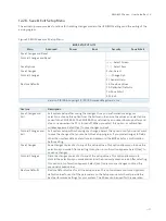
The exit setup menu provides functions for handling changes made to the UEFI BIOS settings and the exiting of the 
setup program. 


Figure 33: BIOS Save & Exit Setup Menu 

BIOS SETUP UTILITY 

Main 

Advanced 

Power 

Boot 

Security 

Save & Exit 

Save Changes and Reset 


Discard Changes and Reset 


: Select Screen 

Save Options 


: Select Item 

Save Changes 


Enter: Select 

Discard Changes 


+/-: Change Opt. 


F1: General Help 

Restore Defaults 


F2: Previous Values 


F3: Optimized Defaults 


F4: Save & Exit 


ESC: Exit 

Version 2.19.1266. Copyright (C) 2018, American Megatrends, Inc. 


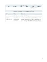
Feature 

Description 

Save Changes and 
Exit 

Exit system setup after saving the changes. Once you are finished making your 
selections, choose this option from the Exit menu to ensure the values you selected are 
saved to the CMOS RAM. The CMOS RAM is sustained by an onboard backup battery and 
stays on even when the PC is turned off. When you select this option, a confirmation 
window appears. Select [Yes] to save changes and exit. 

Discard Changes and 
Exit 

Exit system setup without saving any changes. Select this option only if you do not want 
to save the changes that you made to the Setup program. If you made changes to fields 
other than system date, system time, and password, the BIOS asks for a confirmation 
before exiting. 

Save Changes 

Save changes done so far to any of the setup values. This option allows you to save the 
selections you made. After selecting this option, a confirmation appears. Select [Yes] to 
save any changes. 

Discard Changes 

Discards changes done so far to any of the setup values. This option allows you to 
discard the selections you made and restore the previously saved values. After selecting 
this option, a confirmation appears. Select [Yes] to discard any changes and load the 
previously saved values. 

Restore Defaults 

Restore Default values for all the setup values. This option allows you to load optimal 
default values for each of the parameters on the Setup menus, which will provide the 
best performance settings for your system. The F9 key can be used for this operation. 


Содержание NWA-6500 Series

Страница 1: ...USER GUIDE 1 NWA 6500 Series Doc User Guide Rev 1 4 Doc ID To be Determined...

Страница 2: ...NWA 6500 Series User Guide Rev 1 4 2 This page has been intentionally left blank...

Страница 3: ...no representation or warranty that such application will be suitable for the specified use without further testing or modification We expressly inform the user that this user guide only contains a ge...

Страница 4: ...ions is entirely at your risk To minimize the risks associated with your products and applications you should provide adequate design and operating safeguards You are solely responsible for compliance...

Страница 5: ...contact information refer to our website Customer Support Find our contacts by visiting our website Customer Service As a trusted technology innovator and global solutions provider we extend our embed...

Страница 6: ...d by the law may endanger your life health and or result in damage to your material ESD Sensitive Device This symbol and title inform that the electronic boards and their components are sensitive to s...

Страница 7: ...g any work on this product Earth ground connection to vehicle s chassis or a central grounding point shall remain connected The earth ground cable shall be the last cable to be disconnected or the fir...

Страница 8: ...f it is necessary to store or ship the product then re pack it in the same manner as it was delivered Special care is necessary when handling or unpacking the product See Special Handling and Unpackin...

Страница 9: ...16 2 2 FCC Statement USA 16 2 3 EMC Compliance Canada 16 3 Shipment and Unpacking 17 3 1 Unpacking 17 3 2 Scope of Delivery 17 3 2 1 Standard 17 3 2 2 Optional Parts 17 4 System Overview 18 4 1 Syste...

Страница 10: ...ng the Micro SIM card 32 6 Thermal Considerations 34 6 1 Available Processors 34 6 2 Convection Cooling 34 6 3 System Clearance 34 6 4 Maximum Temperatures 34 6 5 Third Party Components 34 7 Installat...

Страница 11: ...of Acronyms 72 List of Figures Figure 1 Front I O Panel 20 Figure 2 Rear I O Panel 23 Figure 3 Ethernet LED Status 24 Figure 4 Internal view without cover 25 Figure 5 mPCIe mSATA Selection Jumper JP5...

Страница 12: ...rt Console Configuration Legacy Console Redirection Settings 61 Figure 27 BIOS Advanced Menu LAN By Pass Configuration 63 Figure 28 BIOS Advanced Menu H W Monitor 64 Figure 29 BIOS Power Setup Menu 65...

Страница 13: ...ficient air circulation is available to cool the product please ensure that the ventilation openings are not covered or blocked If an air filter is provided this should be cleaned regularly Do not pla...

Страница 14: ...ctly a reliable protective earthing connection is provided a suitable easily accessible disconnecting device is used in the application e g overcurrent protective device if the device itself is not di...

Страница 15: ...Use antistatic mats heel straps or air ionizers for more protection 3 Always handle electrostatically sensitive components by their edge or by their casing 4 Avoid contact with pins leads or circuitry...

Страница 16: ...been tested and found to comply with the limits for a Class B digital device pursuant to Part 15 of the FCC Rules These limits are designed to provide reasonable protection against harmful interferen...

Страница 17: ...3 2 Scope of Delivery 3 2 1 Standard 1x NWA 6500 Series 1x 2 pin Phoenix Plug terminal for models w Phoenix DC In connector 1x Power adapter for models w DC In Jack 1x Power cord for models w DC In J...

Страница 18: ...ector 1x Lockable DC Jack 2x Wi Fi Antenna Port 2x 3G 4G Antenna Port Standard Baseboard and System Expansion Capabilities 1x DDR4 SO DIMM memory socket DIMM1 model w Atom C3338 2x DDR4 SO DIMM memory...

Страница 19: ...ive when mSATA is enabled 4 1 3 System Expansion via M 2 Card Interface The baseboard comes with two onboard M 2 interface connectors One supports Key A Type 22x30 and the other supports Key B type 22...

Страница 20: ...Button see Chapter 4 2 10 11 Clear CMOS Switch Button see Chapter 4 2 11 4 2 1 Power LED The power LED lights up green if the system powered on Prerequisite The system must be attached by means of the...

Страница 21: ...output value of the port GP11 from Super I O is high 4 2 8 Wireless LED The wireless LED blinks green when the data is transferring over the WLAN card or 3G 4G card 4 2 9 User defined LED The user de...

Страница 22: ...NWA 6500 Series User Guide Rev 1 4 22 4 2 11 Clear CMOS Switch Button Find a paper clip or use the pin of a pen to press this button allowing users to clear COMS...

Страница 23: ...8 3G 4G Antenna Port see Chapter 4 3 8 4 3 1 DC In Jack For models with DC In Jack users can connect the supplied power adapter to this jack for converting AC power to DC To prevent damage to the PC...

Страница 24: ...B 3 0 The NWA 6500 Series provides two USB 3 0 2 0 interfaces on the rear I O panel These connectors allow connection of an USB 3 0 or USB 2 0 compatible device to the system 4 3 6 RS232 The console p...

Страница 25: ...see Chapter 4 4 4 7 Micro SIM Card Cage SIM1 see Chapter 4 4 5 8 mPCIe mSATA Selection Jumper JP5 see Chapter 4 4 6 9 M 2 Key B PCIe SATA Selection Jumper JP4 see Chapter 4 4 7 10 mSATA mPCIe fixing b...

Страница 26: ...with a Type 22x42 Type 22x80 SSD card or 3G 4G card which can be switched via the Jumper JP4 see Chapter 4 4 7 The fixing bolt marked in Figure 4 pos 11 can be used to fix either a Type 22x30 card ins...

Страница 27: ...o PCIe USB 3 0 mode for 3G 4G modem card installation or SATA USB 3 0 mode for M 2 SSD installation The default setting is in PCIe USB 3 0 mode Figure 6 M 2 Key B PCIe SATA Selection Jumper JP4 Table...

Страница 28: ...NWA 6500 Series User Guide Rev 1 4 28 2 Fixing bolt for fixing HDD SSD 3 Screw Hole for fixing HDD SSD...

Страница 29: ...this manual Only personnel with appropriate qualifications trainings and authorization are permitted to install and work with the device The installation removal of HHD SSD and or expansion cards may...

Страница 30: ...s 3 Loosen and remove the six Phillips screws three located on the front I O panel and the other three on the rear that secure the access cover to the chassis Retain the screws for later use Figure 8...

Страница 31: ...pansion card mSATA SSD into the corresponding socket Figure 4 pos 4 and rotate it down with the fixing hole of the card over the fixing bolt 4 Press the mPCIe expansion card mSATA SSD down on the side...

Страница 32: ...sponding socket Figure 4 pos 5 pos 6 and rotate it down with the fixing hole of the card over the fixing bolt 4 Press the M 2 SSD M 2 expansion card down on the side with the fixing hole and secure it...

Страница 33: ...des of the socket cover and push down the cover in order to close the cover as shown in Figure 10 6 After closing the cover lock the cover by sliding the closed cover in the direction shown in Figure...

Страница 34: ...ambient temperature depends mostly on the power consumption of the processor and the chipset For the temperature evaluation a specialised tool from Intel was used to set the processor to a defined wo...

Страница 35: ...liability for any and all damages resulting from operation of the unit with foreign objects inside the chassis The NWA 6500 Series has to be installed and operated only by trained and qualified perso...

Страница 36: ...within the range from 19V to 36V Figure 11 Phoenix power plug terminal 1 Slotted pan head screw for securing the wire 2 Slotted pan head screw for securing the Phoenix plug terminal to the Phoenix con...

Страница 37: ...power wires The NWA 6500 Series must be connected DC power supply complying with the SELV Safety Extra Low Voltage requirements of EN 60950 1 standard It must be observed that wiring and short circui...

Страница 38: ...the other ends of the DC power wires to the connections of the DC main power supply Pay attention to the polarity of the connections 4 Switch on the disconnecting device circuit breaker in order to ap...

Страница 39: ...is fully operational when you switch it on for the first time Please pay attention to the following note If you have ordered the NWA 6500 Series without a pre installed operating system you will need...

Страница 40: ...ight soiling clean the NWA 6500 Series with a dry cloth Carefully remove dust from the surface of the cooling fins of the chassis using a clean soft brush Stubborn dirt should be removed using a mild...

Страница 41: ...port Storage Expansion Storage Expansion 1x 2 5 SATA HDD SSD 1x mSATA mPCIe full size mixed w PCIe x1 SATA USB 2 0 1x M 2 Key A mixed w PCIe x1 1x M 2 Key B mixed w SATA USB 2 0 1x Micro SIM Card Hold...

Страница 42: ...ve Software OS Support Windows Server Linux 10 1 Mechanical Specifications Table 8 Mechanical Specifications Construction Aluminum Chassis Dimensions W x D x H 219 mm x 151 mm x 40 mm 8 62 x 5 94 x 1...

Страница 43: ...NWA 6500 Series User Guide Rev 1 4 43 unit mm...

Страница 44: ...ser Guide Rev 1 4 44 10 2 Environmental Conditions Table 9 Environmental Conditions Operating Temperature 0 C 45 C 32 F 113 F Standard 0 C 65 C 32 F 149 F Extended Storage Temperature 20 C 80 C 4 F 17...

Страница 45: ...GND 11 1 2 2 pin Phoenix Connector Table 11 2 pin Phoenix Connector see Figure 2 pos 2 Pin Signal Name DC Jack female 1 19 36Vin 2 GND 11 1 3 VGA Connector Table 12 VGA Connector see Figure 2 pos 3 P...

Страница 46: ...see Figure 2 pos 5 USB 2 0 Contact Pins USB 3 0 Contact Pins 9 pin USB Connector Type A Version 3 0 2 0 Pin Signal Name Pin Signal Name 1 USB_VCC 5 USB_RX 2 USB_D 6 USB_RX 3 USB_D 7 GND 4 GND 8 USB_T...

Страница 47: ...OST messages or splash screen 3 Press the DEL key 4 If the uEFI BIOS is password protected a request for password will appear Enter either the User Password or the Supervisor Password see Security men...

Страница 48: ...e right frame displays an Item Specific Help window providing an explanation of the respective function 12 2 1 Main Setup Menu Upon entering the uEFI BIOS Setup program the Main Setup menu is displaye...

Страница 49: ...ision 24h Processor Cores 2 2 Select Screen Memory Information Select Item Total Size 4096 MB DDR4 Enter Select Frequency 1866 MHz Change Opt F1 General Help System Date Fri 11 30 2018 F2 Previous Val...

Страница 50: ...ctions are included in the menu LAN Configuration FIA HSIO10 Configuration CPU Chipset Configuration NVMe Configuration SATA Configuration USB Configuration Trusted Computing Network Stack Configurati...

Страница 51: ...ting Change Opt Network Stack Configuration F1 General Help Super IO Configuration F2 Previous Values Serial Port Console Redirection F3 Optimized Defaults LAN By Pass Configuration F4 Save Exit H W M...

Страница 52: ...8 PCIE C6139 VGA Lane Disabled PCIE Enabled Select Lane to work as Disabled or PCIE C6139 VGA Lane 18 XHCI A Lane Disabled XHCI Enabled Select Lane to work as Disabled or XHCI A Lane 19 XHCI B Lane Di...

Страница 53: ...d Enabled Select whether to enable or disable the enhanced Cx state of the CPU VMX Disabled Enabled Select whether to enable or disable the Vanderpool Technology VT d Disabled Enabled Select whether t...

Страница 54: ...TILITY Main Advanced Power Boot Security Save Exit NVMe controller and Drive information No NVME Device Found Select Screen Select Item Enter Select Change Opt F1 General Help F2 Previous Values F3 Op...

Страница 55: ...nabled F1 General Help F2 Previous Values F3 Optimized Defaults F4 Save Exit ESC Exit Version 2 19 1266 Copyright C 2018 American Megatrends Inc Feature Option Description SATA Controller 0 Enabled Di...

Страница 56: ...F4 Save Exit ESC Exit Version 2 19 1266 Copyright C 2018 American Megatrends Inc Feature Option Description Legacy USB Support Enabled Disabled Auto Select whether to enable or disable Legacy USB sup...

Страница 57: ...Select Screen Select Item Enter Select Change Opt F1 General Help F2 Previous Values F3 Optimized Defaults F4 Save Exit ESC Exit Version 2 19 1266 Copyright C 2018 American Megatrends Inc Feature Opt...

Страница 58: ...le Network Protocol Intel I210 AT 2 LAN Boot X553 1GbE 1 Disabled Load PXE Select whether to enable or disable load onboard PXE Preboot Execution Environment or uEFI SNP Simple Network Protocol Intel...

Страница 59: ...BIOS SETUP UTILITY Main Advanced Power Boot Security Save Exit Serial Port 1 Configuration Serial Port Enabled Select Screen Device Settings IO 3F8h IRQ 4 Select Item Enter Select Change Setting Auto...

Страница 60: ...atrends Inc Feature Option Description Console Redirection Disabled Enabled Select whether to enable or disable console redirection Figure 25 BIOS Advanced Menu Serial Port Console Configuration COM1...

Страница 61: ...e receiving buffers are full a stop signal can be sent to stop the data flow Once the buffers are empty a start signal can be sent to re start the flow Software flow control uses start stop ASCII char...

Страница 62: ...on COM Port COM1 COM2 Disabled Select a COM port to display redirection of Legacy OS and Legacy OPROM Messages Resolution 80x24 80x25 Select the number of rows and columns supported redirection on leg...

Страница 63: ...Power On Off Enter Select Change Opt F1 General Help F2 Previous Values F3 Optimized Defaults F4 Save Exit ESC Exit Version 2 18 1263 Copyright C 2018 American Megatrends Inc Feature Option Descriptio...

Страница 64: ...Health Status CPU Temperature DTS 51 C Select Screen CPU Temperature Thermal 49 C Select Item System Temperature 39 C Enter Select Change Opt VCORE 1 053 V F1 General Help 5V 5 106 V F2 Previous Valu...

Страница 65: ...re AC Power Loss Power Off Power On Last State Select AC power state when power is re applied after a power failure Select Power Off if you want the system to remain off after power restored Select Po...

Страница 66: ...FW MagicPacket Resume LAN I210 AT 2 Disabled OS Driver FW MagicPacket Select whether to enable wake from LAN device Intel I210 AT 2 Resume By RTC Alarm Disabled Enabled Select whether to enable or dis...

Страница 67: ...Mode Minute Select Item WDT Timer 3 Enter Select Change Opt F1 General Help F2 Previous Values F3 Optimized Defaults F4 Save Exit ESC Exit Version 2 19 1266 Copyright C 2018 American Megatrends Inc Th...

Страница 68: ...ure Option Description Full Screen LOGO Display Disabled Enabled Select whether to enable or disable to display logo screen Bootup NumLock State On Off Select the state of the NumLock feature of the k...

Страница 69: ...this is a power on password and must be entered to boot or enter Setup In Setup the User will have Administrator rights The password length must be in the following range Select Screen Minimum Length...

Страница 70: ...ecord of all passwords in a safe place Forgotten passwords results in being locked out of the system If the system cannot be booted because the User Password or the Supervisor Password are not know co...

Страница 71: ...s option a confirmation window appears Select Yes to save changes and exit Discard Changes and Exit Exit system setup without saving any changes Select this option only if you do not want to save the...

Страница 72: ...et HDD Hard Disk Drive HDMI High Definition Multimedia Interface LAN Local Area Network LED Light Emitting Device LVDS Low Voltage Differential Signaling ME F W Management Engine Firmware mPCIe mini P...

Страница 73: ...NWA 6500 Series User Guide Rev 1 4 73...

Отзывы: