I
KEEX-5100 Series User’s Manual
KEEX-5100 Series
Intel
®
Embedded Compact Extended Form Factor
with Intel
Haswell / Broadwell ULT Processors
User’s Guide
Страница 1: ...I KEEX 5100 Series User s Manual KEEX 5100 Series Intel Embedded Compact Extended Form Factor with Intel Haswell Broadwell ULT Processors User s Guide...
Страница 2: ...atent rights of Quanmax nor the rights of others Quanmax is a registered trademark of Quanmax All trademarks registered trademarks and trade names used in this user s guide are the property of their r...
Страница 3: ...r Computer 13 Chapter 1 Introduction 16 Overview 16 Product Specifications 17 System Block Diagram 18 Mechanical Dimensions 19 Chapter 2 Hardware Settings 20 Overview 20 Jumper Settings and Pin Defini...
Страница 4: ...Content 4 KEEX 5100 Series User s Manual Appendix A DIO Digital I O Sample Code 53 Appendix B WatchDog Timer Sample Code 56...
Страница 5: ...8 Figure 2 Mechanical Dimensions 19 Figure 3 Jumper Connector 20 Figure 4 Jumper and Connector Locations 21 Figure 5 Rear Panel IO 31 Figure 6 Align the SO DIMM Memory Module with the onboard socket 3...
Страница 6: ...Channel 2W Audio AMP Output Wafer 25 Table 16 CN9 Audio Pin Header 25 Table 17 CN10 Digital Input Output Wafer 26 Table 18 CN15 RS 232 422 485 Port 1 Wafer 26 Table 19 CN16 RS 232 422 485 Port 1 Wafe...
Страница 7: ...ced Menu Super IO Configuration 40 Table 44 Advanced Menu Super IO Configuration Serial Port 1 Configuration 40 Table 45 Advanced Menu Super IO Configuration Serial Port 2 Configuration 41 Table 46 Ad...
Страница 8: ...odily harm Use extreme caution when installing or removing components Refer to the installation instructions in this user s guide for precautions and procedures If you have any questions please contac...
Страница 9: ...pins Also before connecting a cable make sure both connectors are correctly oriented and aligned CAUTION Do not attempt to service the system yourself except as explained in this user s guide Follow...
Страница 10: ...sensitive components at an ESD workstation If possible use antistatic floor pads and workbench pads Handle components and boards with care Don t touch the components or contacts on a board Hold a boa...
Страница 11: ...amage If there is damage notify Quanmax customer service immediately Refer to Warranty Policy for the return procedure Regulatory Compliance Statements This section provides the FCC compliance stateme...
Страница 12: ...accident acts of God or other causes beyond the control of Quanmax or the manufacturer Neglect misuse and abuse shall include any installation operation or maintenance of the product other than in ac...
Страница 13: ...uct furnished hereunder Quanmax s liability shall in no event exceed the purchase price of the product purchased hereunder The foregoing limitation of liability shall be equally applicable to any serv...
Страница 14: ...form at reduced efficiency Power Protection The greatest threats to a system s supply of power are power loss power spikes and power surges caused by electrical storms which interrupt system operation...
Страница 15: ...e power to the system for a limited amount of time depending on the UPS system UPS systems range in price from a few hundred dollars to several thousand dollars with the more expensive unit s allowing...
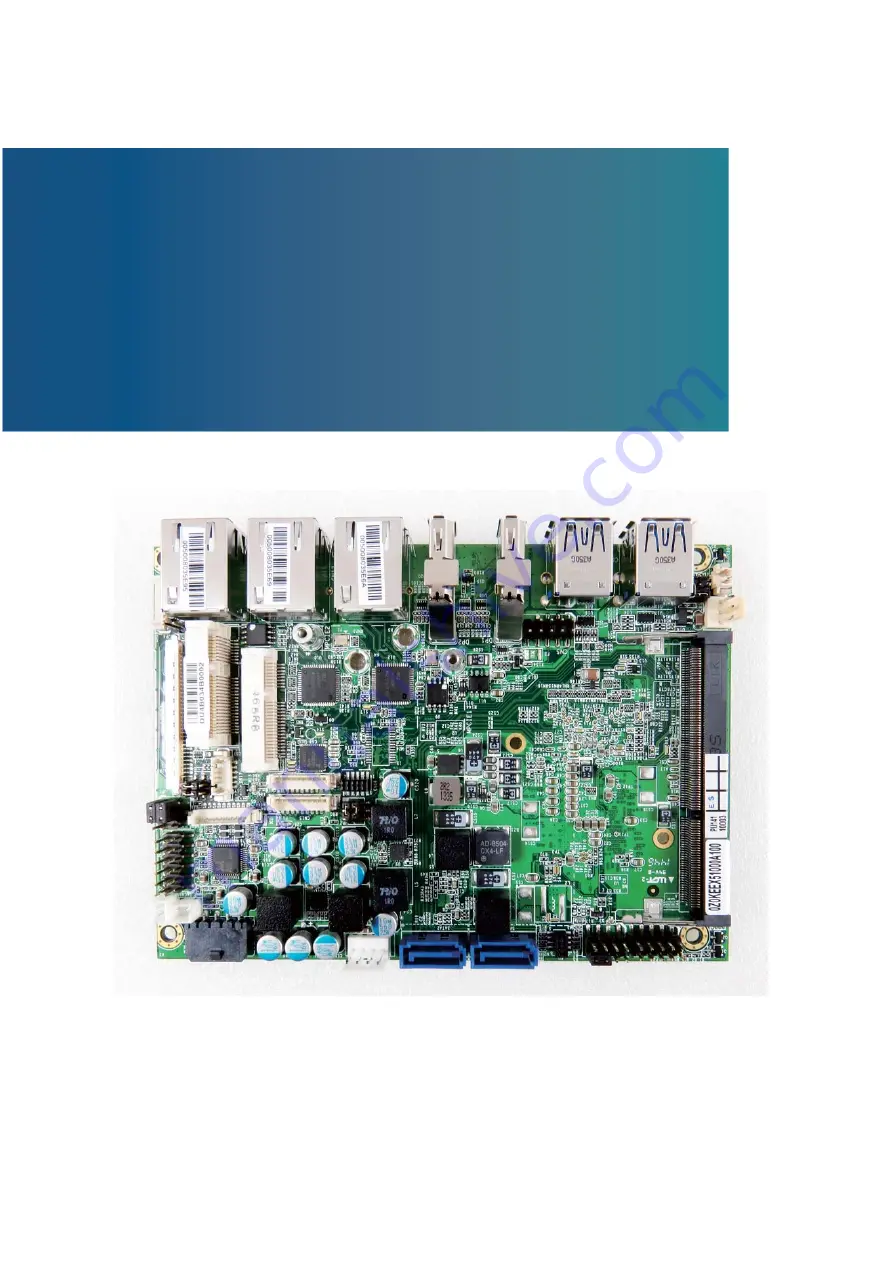
Страница 16: ...IMM socket 2x DP 1x LVDS 1x DIO 3x Gigabit Ethernet 2x SATA 1x mSATA 2x mini PCIe slot 4x USB2 0 1x USB3 0 and 2x COM Checklist Driver Manual CD Quick Installation Guide KEEX 5100 Series main board 1x...
Страница 17: ...3W Audio Amplifier onboard 2x Wafers for Stereo Speaker output Peripheral Support Storage supported z 2x SATA 7P connector z 1x mSATA mixed with mPCIe socket USB z 4x USB3 0 port z 2x USB2 0 ports FAN...
Страница 18: ...apter 1 18 KEEX 5100 Series User s Manual Storage Temp 20 C 80 C 4 F 176 F Humidity 0 95 Certifications CE FCC Class A Table 1 KEEX 5100 Series Specification System Block Diagram Figure 1 Block Diagra...
Страница 19: ...Chapter 1 19 KEEX 5100 Series User s Manual Mechanical Dimensions A 3 5mm B 5 08mm C 2 6mm Figure 2 Mechanical Dimensions...
Страница 20: ...tion Figure 3 Jumper Connector For a three pin jumper see Figure 3 the jumper setting is designated 1 2 when the jumper connects pins 1 and 2 The jumper setting is designated 2 3 when pins 2 and 3 are...
Страница 21: ...Chapter 2 21 KEEX 5100 Series User s Manual Jumper Settings and Pin Definitions For jumper and connector locations please refer to the diagrams below Figure 4 Jumper and Connector Locations...
Страница 22: ...ecurity Over ride JP7 RTC Reset Selection JP8 SRTC Reset Selection Table 3 JP1 Panel Backlight Power Selection for LVDS1 2 1 6 5 Jumper Setting Status 1 1 3 Backlight Power 12V 3 5 Backlight Power 5V...
Страница 23: ...off in Deep S5 state DIP 3P 1R MALE STRAIGHT TYPE Pitch 2 0mm YIMTEX 3291 03SAGR 6T Table 8 JP6 Flash Description Security Over ride 1 2 Jumper Status 1 2 Open Disabled 1 2 Short Enabled Pitch 2 54mm...
Страница 24: ...n Header CN10 Digital Input Output Pin Header CN14 P80_Header CN15 RS 232 422 485 Port 1 Wafer CN16 RS 232 422 485 Port 2 Wafer CN17 SIM Interface Wafer for MPCIE2 CN18 Backlight Power Output Wafer fo...
Страница 25: ...SB_A 6 USB_B 7 GND 8 GND 9 KEY 10 GND Pitch 2 54mm YIMTEX 3362 05SANGR 09 The power source of USBVCC can be selected by JP7 Table 14 CN7 Right Channel 2W Audio AMP Output Wafer Pin Signal Name 1 Speak...
Страница 26: ...ort 1 Wafer Pin RS 232 RS 422 Half Duplex RS 485 Full Duplex RS 485 1 DCD TX DATA TX 2 DSR TX DATA TX 3 RXD RX N A RX 4 RTS RX N A RX 5 TXD N A N A N A 6 CTS N A N A N A 7 DTR N A N A N A 8 RI N A N A...
Страница 27: ...m Pinrex 712 73 06TWB0 Table 21 CN18 Backlight Power Output Wafer for LVDS1 Pin Signal Name 1 BL_ADJ_PWM 2 BL_ADJ_VOL 3 GND 4 5V 12V 5 5V 12V 6 GND 7 BL_EN Pitch 1 25mm YIMTEX 501MW1X07MTR 1R BL_ADJ c...
Страница 28: ...2 Pin Header Pin Signal Pin Signal 1 Power LED 2 Power Button 3 NC 4 Power Button 5 Power LED 6 SMBALERT 7 BATLOW 8 SMBus Data 9 GND 10 SMBus Clock Pitch 2 54mm YIMTEX 3362 05SANGR Table 26 LVDS1 Pri...
Страница 29: ...16 NC Reserved 17 18 Ground Reserved 19 20 W_Disable Ground 21 22 PERST PERn0 23 24 3 3VSB PERp0 25 26 Ground Ground 27 28 1 5V Ground 29 30 SMB_CLK PETn0 31 32 SMB_DATA PETp0 33 34 Ground Ground 35 3...
Страница 30: ...PERST PERn0 23 24 3 3VSB PERp0 25 26 Ground Ground 27 28 1 5V Ground 29 30 SMB_CLK PETn0 31 32 SMB_DATA PETp0 33 34 Ground Ground 35 36 USB_D Ground 37 38 USB_D 3 3VSB 39 40 Ground 3 3VSB 41 42 LED_WW...
Страница 31: ...onnector CN3 USB3 0 Port 2 3 Connector CN11 GbE LAN1 RJ 45 Connector CN12 GbE LAN2 RJ 45 Connector CN13 GbE LAN3 RJ 45 Connector DP1 DP Connector DP2 DP Connector CN4 Power Input Wafer Table 32 CN2 US...
Страница 32: ...d by JP5 Table 34 CN11 GbE LAN1 RJ 45 Connector Pin Signal Name Pin Signal Name 1 TX1 5 TX3 2 TX1 6 TX2 3 TX2 7 TX4 4 TX3 8 TX4 RJ45 TFM LED 10 100 1000 14P DIP 90 UDE RT7 174AAM1A XA Table 35 CN12 Gb...
Страница 33: ...1 16 GND 7 TX2 17 AUX 8 GND 18 HPD 9 TX2 19 GND 10 TX3 20 PWR Table 38 DP2 DisplayPort Port 2 Connector Pin Signal Pin Signal 1 TX0 11 GND 2 GND 12 TX3 3 TX0 13 GND 4 TX1 14 GND 5 GND 15 AUX 6 TX1 16...
Страница 34: ...damaging the SO DIMM ground yourself by touching a grounded metal surface or use a ground strap before you touch the SO DIMM 2 Do not touch the connectors of the SO DIMM Dirt or other residue may cau...
Страница 35: ...e module Figure 7 Press down on the SO DIMM Memory Module to lock it in place Removing a SO DIMM To remove the SO DIMM use your fingers or a small screwdriver to carefully push away the tabs that secu...
Страница 36: ...please contact Quanmax AMI s ROM BIOS provides a built in Setup program which allows the user to modify the basic system configuration and hardware parameters The modified data will be stored in a bat...
Страница 37: ...Table 40 KEEX 5100 BIOS Main Menu BIOS SETUP UTILITY M a i n A d v a n c e d B o o t S e c u r i t y S a v e E x i t Product Information Select Screen 6HOHFW WHP Enter Select Change Opt F1 General Hel...
Страница 38: ...oot Disabled Onboard LAN3 Controller Enabled Onboard LAN3 Boot Disabled Audio Controller Enabled Display Configuration Super IO Configuration CPU Chipset Configuration SATA Configuration USB Configura...
Страница 39: ...s F4 Save Exit ESC Exit UMA Frame Buffer Size 256 MB DVMT Pre Allocated 64M DVMT Total Gfx Mem 256 M Primary IGFX Boot Display Active LVDS VBIOS Default Disabled Version 2 17 1246 Copyright C 2015 Ame...
Страница 40: ...rial Port 1 Configuration BIOS SETUP UTILITY M a i n Ad v a n c e d B o o t C h i p s e t P o w e r S e c u r i t y E x i t Serial Port 1 Configuration Serial Port Enabled Device Settings IO 3F8h IRQ...
Страница 41: ...Change Settings Auto Serial Port 2 Type RS232 Select Screen 6HOHFW WHP Enter Select Change Opt F1 General Help F2 Previous Values F3 Optimized Defaults F4 Save Exit ESC Exit Version 2 17 1246 Copyrigh...
Страница 42: ...nabled Disabled Package power linit Enabled Cpu Power Limit1 0 Cpu Power Limit1 Time 0 Cpu Power Limit2 20 Platform power limit lock Enabled Cpu Power Limit3 0 Cpu Poer Limit3 Time 0 Cpu Power Limit D...
Страница 43: ...ions 0 Cpu Power limit2 Options 20 Platform power limit lock Options Disabled Enabled Cpu Power limit3 Options 0 Cpu Power limit3 Time Options 0 Cpu Power limit3 Duty Cycle Options 0 DDR Power limit1...
Страница 44: ...TA Controller s Enabled SATA Mode Selection AHCI SATA Controller Speed Default Serial ATA Port 1 Empty Port 2 Serial ATA Port 2 Enabled Empty Port 2 Enabled mSATA Port 1 Port 1 Sandisk SSD U1 32 0GB E...
Страница 45: ...on 2 17 1246 Copyright C 2015 American Megatrends Inc Legacy USB Support Options Disabled Enabled Auto XHCI Legacy Support Options Disabled Enabled XHCI hand off Options Disabled Enabled EHCI hand off...
Страница 46: ...t Change Opt F1 General Help F2 Previous Values F3 Optimized Defaults F4 Save Exit ESC Exit User Configuration Disabled DI_1 DI_2 DI_3 DI_4 1 1 1 1 DO_1 DO_2 DO_3 DO_4 1 1 1 1 Version 2 17 1246 Copyri...
Страница 47: ...guration CPU Temperature 80 C Memory Temperature 64 C System Temperature 54 C CPU Fan Speed N A VCORE 1 711 V VIN 12 000 V 5V 5 114 V 3 3V 3 372 V Select Screen 6HOHFW WHP Enter Select Change Opt F1 G...
Страница 48: ...Off Power Saving Mode Disabled Resume Event control Resume By PCIE Device Disabled Resume By RTC Alarm Disabled Watchdog Timer Configuration Version 2 17 1246 Copyright C 2015 American Megatrends Inc...
Страница 49: ...out 1 Bootup NumLock State On CSM Support Boot Option Filter Enabled Legacy Only Boot Option Priorities Boot Option 1 P3 SanDisk SSD U110 32GB Hard Drive BBS Priorities Version 2 17 1246 Copyright C 2...
Страница 50: ...rd User Password HDD Security Configuration P3 SanDisk SSD Secure Boot menu Select Screen 6HOHFW WHP Enter Select Change Opt F1 General Help F2 Previous Values F3 Optimized Defaults F4 Save Exit ESC E...
Страница 51: ...BIOS asks for a confirmation before exiting Discard Changes Discards changes done so far to any of the setup values This option allows you to discard the selections you made and restore the previousl...
Страница 52: ...onnected the appropriate power source power it up using the power supply and install the desired operating system You can download the drivers for the KEEX 5100 Series from the Quanmax website at www...
Страница 53: ...F1B bit7 DO_3 IOport 0x1E7B bit8 DI_3 IOport 0x1F23 bit7 DO_4 IOport 0x1D73 bit8 DI_4 IOport 0x1F2B bit7 int main int RetVal int i int Temp Temp1 Temp2 Temp3 Temp4 Clear DO_1 4 RetVal inp 0x1EC3 IO Po...
Страница 54: ...tVal Setting DO_2 High RetVal inp 0x1E7B IO Port 0x1E7B RetVal RetVal 0x80 outp 0x1E7B RetVal Setting DO_3 High RetVal inp 0x1D73 IO Port 0x1D73 RetVal RetVal 0x80 outp 0x1D73 RetVal Setting DO_4 High...
Страница 55: ...Appendix A 55 KEEX 5100 Series User s Manual Temp4 RetVal 0x40 6 DI_4 value printf DI_1 d n Temp1 printf DI_2 d n Temp2 printf DI_3 d n Temp3 printf DI_4 d n Temp4 system pause return 0...
Страница 56: ...455 Ti Ding Blvd Sec 2 Neihu District Taipei Taiwan 114 Phone 886 2 2799 2789 KEEX 5100 DOS Watchdog sample program Please compile with Turbo C 3 0 to utilized the program include stdio h define SIO_...
Страница 57: ...ATA outp SIO_CONFIG_DATA value 0x40 Set Timer unit 0xF5 bit3 0 1sec 1 60 sec of watchdog timer by setting this bit outp SIO_CONFIG_INDEX 0xF5 value inp SIO_CONFIG_DATA outp SIO_CONFIG_DATA value 0xF7...