background image

15

March 26, 2020

7039-802B

Negative pressure results from the imbalance of air available 

for the appliance to operate properly. It can be strongest in 

lower levels of the house.

Causes include:

• 

Exhaust fans (kitchen, bath, etc.)

•  Range hoods

• 

Combustion air requirements for furnaces, water 

appliances and other combustion appliances

•  Clothes dryers

•  Location of return-air vents to furnace or 

air conditioning

• 

Imbalances of the HVAC air handling system

•  Upper level air leaks such as:

 - Recessed lighting

 - Attic hatch

 - Duct leaks

To minimize the effects of negative air pressure:

•  Install the outside air kit with the intake facing prevailing 

winds during the heating season

• 

Ensure adequate outdoor air for all combustion 

appliances and exhaust equipment

•  Ensure furnace and air conditioning return vents are 

not located in the immediate vicinity of the appliance

•  Avoid installing the appliance near doors, walkways or 

small isolated spaces

• 

Recessed lighting should be a “sealed can” design

•  Attic hatches weather stripped or sealed

•  Attic mounted duct work and air handler joints and 

seams taped or sealed

K. Negative Pressure
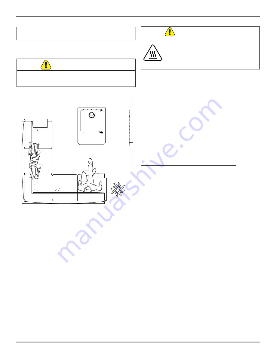
J. Clear Space

Figure 15.1

Maintain 4 ft (1.22m) clearance to 

combustible in front of appliance 

WARNING

Asphyxiation Risk.

•  Negative pressure can cause spillage 

of combustion fumes, soot and 

carbon monoxide.

•  Appliance needs to draft properly 

for safety.

WARNING

Do NOT place combustible objects in front of the 

appliance. High temperatures may ignite clothing, 

furniture or draperies.

NOTE:

 Do NOT place combustible objects within 

4 ft (1.2m) of the front of appliance 

(Figure 15.1)

.

•  Mantel:

Avoid placing candles and other heat-sensitive objects 

on mantel or hearth. Heat may damage these objects.

Содержание MILLENNIUM 2100 Series

Страница 1: ...s appliance Alert children and adults to hazards of high temperatures High temperatures may ignite clothing or other flammable materials Keep clothing furniture draperies and other flammable materials...

Страница 2: ...8 in USA Fuel loading door 5 3 4 in 2 1 4 in 29 5 8 in minimum 39 in minimum CANADA 203mm 8 in 203mm 8 in 203mm 8 in 457mm 18 in 1245mm 49 in minimum 1006mm 39 5 8 in minimum Made in U S A of US and i...

Страница 3: ...ion 7 C BTU Efficiency Specifications 7 D Glass Specifications 8 E Mobile Home Approved 8 F Sleeping Room 8 G California Prop65 8 2 Operating Instructions 9 A Over Firing Your Appliance 9 B Wood Selec...

Страница 4: ...nction boxes wire harnesses transformers and lights excluding light bulbs X X Molded Refractory Panels Glass Liners X Vent Free Burners Vent Free Logs X X Castings Medallions and Baffles 6 years 3 yea...

Страница 5: ...ot covered by this warranty Limited Catalyst Warranty o For wood burning products containing a catalyst the catalyst will be warranted for a six year period to the original purchaser at catalyst WARRA...

Страница 6: ...DD KINDLING LIGHT THE PAPER ADD MORE WOOD REDUCE AIR CONTROLS Set to desired heat output LOW BURN RATE CONTROL Upper Right Corner AUTOMATIC COMBUSTION CONTROL ACC Middle right hand side LOW The applia...

Страница 7: ...k BTU Hour Output 44 400 Vent Size 6 inches Firebox Size 1 48 cubic feet Recommended Log Length 16 inches Fuel Seasoned Cord Wood 20 moisture Weighted average LHV Low Heating Value efficiency using Do...

Страница 8: ...t be maintained The appliance must be properly grounded to the frame of the mobile home with 8 copper ground wire and chimney must be listed to UL103 HT or a listed UL 1777 full length six inch 152mm...

Страница 9: ...h enough to evaporate the moisture which is present in all wood The wood will reach the boiling point of water 212 F and will not get any hotter until the water is evaporated This process takes heat f...

Страница 10: ...next stage of burning the secondary stage is the period when the wood gives off flammable gases which burn above the fuel with bright flames During this stage of burning it is very important that the...

Страница 11: ...e knob is located under the high position Figure 11 1 2 Maximize Heat with The ACC System To maximize heat output with the ACC timer System or also known as high burn push the ACC Air Control lever to...

Страница 12: ...etting Burn Rate Air Control spring handle up to high position for 5 minutes Then activate the ACC timer system by pushing the knob all the way back toward the appliance to HI then pull forwards towar...

Страница 13: ...e appliance NEVER light or rekindle fire with kerosene gasoline or charcoal lighter fluid the results can be fatal 6 Once the kindling is burning quickly add several full length logs 3 inches 76mm or...

Страница 14: ...tion If you find the blower coming on and off at undesirable temperatures relocate the snap disc to another location in the designated zone on the back of the appliance Figure 14 1 There is a manual o...

Страница 15: ...e furnace and air conditioning return vents are not located in the immediate vicinity of the appliance Avoid installing the appliance near doors walkways or small isolated spaces Recessed lighting sho...

Страница 16: ...TACT YOUR DEALER for additional information regarding operation and troubleshooting Visit www quadrafire com to find a dealer L Frequently Asked Questions WARNING Fire Risk DO NOT BURN GARBAGE OR FLAM...

Страница 17: ...four 4 cords of wood The chimney and chimney cap must be inspected for soot and creosote every two months during the burn season or more frequency if chimney exceeds or is under 14 16 ft 4 3m 4 8m me...

Страница 18: ...y connector and chimney should be inspected once every 2 months during the heating season to determine if a creosote or soot buildup has occurred If creosote or soot has accumulated it should be remov...

Страница 19: ...he glass helping to keep smoke from adhering to its surface When operated at a low burn rate less air will be flowing over the glass and the smokey relatively cool condition of a low fire will cause t...

Страница 20: ...tact with the back of the firebox and even with each other in the front Ceramic Blanket Back of Firebox Baffle Board Baffle Retainer Bracket WARNING Fire Risk Firebox damage due to improper baffle pla...

Страница 21: ...n page 13 of the Installation manual Open window below the appliance towards the wind Wood condition is too wet too large Use dry seasoned wood refer to Wood Selection Storage on page 9 Bed of coals n...

Страница 22: ...er or will permanently stain glass on next firing Refer to maintenance instructions NOTE Replace with 5mm ceramic glass only Service Part SRV7000 013 1 Ensure that the fire is out and the appliance is...

Страница 23: ...art SRV230 0470 1 Locate the snap disc bracket assembly at the bottom left rear corner of the appliance 2 A magnet holds the bracket to the appliance Pull the bracket down away from the appliance to e...

Страница 24: ...e ceramic blanket 4 Re install the baffle pieces one piece at a time Be sure the baffle boards are even with the front manifold tube and is resting on all tubes Figure 24 3 and Figure 24 4 5 To re ins...

Страница 25: ...order to replace the tube channel assembly a clearance of 19 inches 483mm is required on the right side of appliance in order to remove the tubes with the appliance in place If space is not available...

Страница 26: ...26 March 26 2020 7039 802B 6 Reference Materials A Service and Maintenance Log Date of Service Performed By Description of Service...

Страница 27: ...Service Parts 21M ACC C Beginning Manufacturing Date Jan 2020 Ending Manufacturing Date Active R Part number list on following pages 2100 Millennium Wood Stove Advanced Combustion Control ACC 02 20 1...

Страница 28: ...1 4 Qty 9 Req 832 0550 Pkg of 6 832 3040 4 2 Brick 5 3 4 x 4 1 2 x 1 1 4 Qty 3 Req SRV7128 039 4 3 Brick 8 x 4 1 2 x 1 1 4 Qty 2 Req SRV7128 022 4 4 Brick see diagram Qty 1 Req SRV7128 619 4 5 Brick...

Страница 29: ...13 16 in H SRV7000 013 Y Gasket Glass Tape Field cut to Size 5 Ft Length 832 0460 Y 10 4 Frame Glass GL FRM 21M 10 5 Screw Flat Head Philips 8 32 x 1 2 Pkg of 12 220 0490 12 Y 11 Door Handle Assembly...

Страница 30: ...y Side Right SRV7039 002 17 Tube Channel Top Access Cover SRV7039 114 Component Pack 7039 011 18 1 Burn Rate Control Assembly 7039 016 18 2 Spring Handle 1 4 Black SRV7000 614 Y 18 3 Timer Air Control...

Страница 31: ...er Control Box W Switch SRV7000 194 Y Blower Convection 812 4900 Y Component Pack 7033 051 Snap Disc Bracket Assembly SRV7033 036 Snap Disc 1 Convection Blower SRV230 0470 Y Wire Harness Blower 7033 2...

Страница 32: ...and maintenance instructions included Read understand and follow these instructions for safe installation and operation Leave this manual with party responsible for use and operation of this appliance...

Отзывы: