background image

AH20 Robot User Manual 

24                                                                                                                            Document Version V1.0.1 (11-14-2022) 


Chapter 4


Introduction to Electrical Connectors 

4.1


External electrical connector 

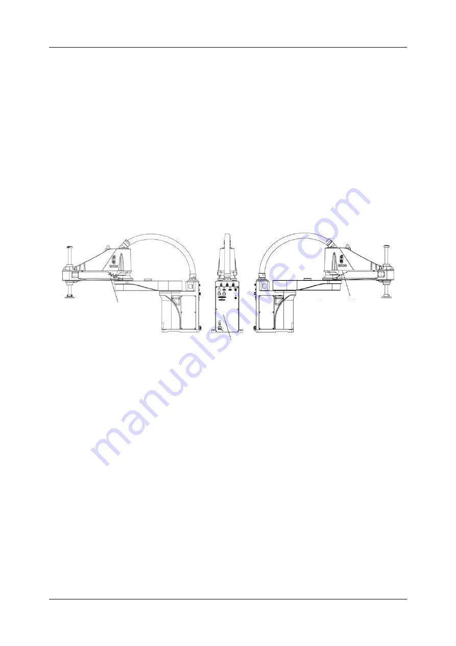
The electrical connectors of AH20 Robot mainly include air pipe connector, 

power connector, communication connector and user connector, etc., which are 

distributed on the base and mechanical arm 2, as shown in the figure. 


Figure 4-1 External connector panel 

4.1.1


Connector panel of the mechanical arm 2 

The mechanical arm 2 connectors are arranged on both sides of the arm in 

sequence,  including  the  air  pipe  connector  and  the  CS  connector,  which  are 

hidden  under  the  arm,  showing  a  beautiful  appearance  and  design  without 

destroying the external streamline. 

Connector panel of the mechanical 

arm 2 

Base connector panel


Connector panel of the mechanical 

arm 2 

Содержание AH20

Страница 1: ......

Страница 2: ...User Manual AH20 0850 0204 2000 AH20 0850 0204 4000 AH20 1050 0204 2000 AH20 1050 0204 4000 QKM Technology Dongguan Co Ltd Document version V1 0 1 Issued on November 14 2022...

Страница 3: ......

Страница 4: ...ion guide system debugging and technical specifications of AH20 Robot so that users can fully understand and properly use the robot Target readers This manual is for the reference of Customer Engineer...

Страница 5: ...in death or serious injury It indicates that a potentially dangerous situation would occur and cause personal injuries or equipment damage if it is not avoided It indicates that an unpredictable situ...

Страница 6: ...manufacture process and use this product and related parts Trademark statement is the trademark of QKM and QKM possesses the ownership of the trademark Disclaimer QKM takes no responsibility for direc...

Страница 7: ...Technology Dongguan Co Ltd Headquarters Tower A Building 17 Headquarters 1 No 4 Xinzhu Road Songshan Lake High tech Industrial Development Zone Dongguan City Tel 86 0769 27231381 Fax 86 0769 27231381...

Страница 8: ...updated contents of all previous document versions Document version Issued on Revised content V1 0 0 June 7 2022 The first version V1 0 1 November 14 2022 Modified the front pinout picture of the 9 pi...

Страница 9: ...tions 1 1 1 General safety 1 1 2 Precautions for safe operation 3 1 3 Safety signs 4 Chapter 2 Product Overview 6 2 1 Introduction 6 2 2 Model implication 7 2 3 Product features 8 Chapter 3 Components...

Страница 10: ...1 External electrical connector 24 4 1 1 Connector panel of the mechanical arm 2 24 4 1 2 Base connector panel 26 4 2 Indicator description 28 4 2 1 Main power indicator 28 4 2 2 System indicator Mech...

Страница 11: ...andling of robot 47 5 6 Base installation 49 5 7 5 7 Removal of fastener 50 5 8 Ground protection 51 5 9 Installation of robot cable 52 5 9 1 Communication connection 53 5 9 2 Connection of E stop dev...

Страница 12: ...instructions 73 6 4 7 Run instructions 74 6 4 8 Breakpoint debugging 75 6 4 9 Output 75 6 4 10 Clear output 76 6 4 11 Save output 76 6 5 Manual jog teach 77 6 6 Servo power on 80 6 7 Speed adjustment...

Страница 13: ...H20 0850 0204 2000 dimensions unit mm 16 Figure 3 8 AH20 0850 0204 2000 dimensions unit mm 16 Figure 3 9 AH20 0850 0204 4000 dimensions unit mm 17 Figure 3 10 AH20 0850 0204 4000 dimensions unit mm 17...

Страница 14: ...at the back of the base 44 Figure 5 2 Installation diagram 45 Figure 5 3 Installation position of external parts unit mm 46 Figure 5 4 Camera installation diagram 47 Figure 5 5 Schematic diagram of pa...

Страница 15: ...r panel 27 Table 4 3 Description of power indicator status 28 Table 4 4 Description of system indicator status 28 Table 4 5 Definition of power connector pins 29 Table 4 6 Definition of auxiliary enco...

Страница 16: ...elevant institutions or shall have the same professional skills Personnel shall read this manual carefully before conducting operation maintenance teaching programming and system development of AH20 R...

Страница 17: ...nt temperature is close to 0 operate the robot at the speed of 10 or less for more than 10 minutes to preheat it perform other operations after preheating the robot Detergents with strong corrosion ar...

Страница 18: ...robot damage may be caused If users request for transport please adopt the standard packaging required by QKM 1 2 Precautions for safe operation Shut off the power when installing and maintaining the...

Страница 19: ...Users should carry out daily check and regular maintenance of the robot according to the manual and related requirements and timely replace damaged parts to ensure safe operation and service life of...

Страница 20: ...ety Precautions Document Version V1 0 1 11 14 2022 5 1 A triangle sign for warning of high voltage 2 Grounding sign 3 Do not disassemble the robot to prevent failures 4 A sign for protection from resi...

Страница 21: ...referred to as QKM It is characterized by AIO design no separate control cabinet and with compact structure greatly overthrowing the layout of traditional industrial robots with large control cabinet...

Страница 22: ...tion Table 2 1 Model preview Model Name Rated load kg Max Load kg Horizontal Work Space mm Vertical Work Space mm Installation Protection Grade Operating Environment AH20 0850 0204 2000 10 20 850 200...

Страница 23: ...without separate control cabinet for less space and easy installation By adopting a new generation of distributed architecture control system it is more stable smoother and easier to use Built in cont...

Страница 24: ...corrugated pipe including cables Its appearance and structure are shown in Figure 3 1 Figure 3 1 Composition of AH20 Robot AH20 0850 0204 2000 3 1 1 Base The connector panel of power supply communicat...

Страница 25: ...nd rotating shaft Axis J3 and Axis J4 are driven by synchronous belt with high stability and reliability Mechanical arm 2 is overall designed with compact structure As the spline screw shaft is expose...

Страница 26: ...6 mm 2 Electrical connector panel For connecting power supply Ethernet cables etc 3 I O connector 19 core circular aviation plug 4 Grooved handrail Convenient for users to handle the robot 5 Double b...

Страница 27: ...robot is in servo off state For details on the electrical connector panel please refer to Section 4 1 Introduction of connector panel 3 2 Trajectory Joint coordinate of robot control system The postu...

Страница 28: ...and Functional Description Document Version V1 0 1 11 14 2022 13 3 3 Horizontal work space AH20 0850 0204 2000 AH20 0850 0204 4000 Figure 3 4 AH20 0850 0204 2000 AH20 0850 0204 4000 AH20 1050 0204 200...

Страница 29: ...AH20 Robot User Manual 14 Document Version V1 0 1 11 14 2022 Figure 3 5 AH20 1050 0204 2000 AH20 1050 0204 4000...

Страница 30: ...V1 0 1 11 14 2022 15 3 4 Robot coordinate system The and indicating directions of the axes are applicable to the cartesian coordinate system Figure 3 6 World coordinate system 3 5 Specification and d...

Страница 31: ...Figure 3 8 AH20 0850 0204 2000 dimensions unit mm AH20 0850 0204 4000 The moving bellows will arch to the left by up to 940 mm Up to 795 mm The maximum stroke of the screw can reach 200 mm 150 mm spac...

Страница 32: ...00 dimensions unit mm Figure 3 10 AH20 0850 0204 4000 dimensions unit mm Through hole Through hole Through hole The moving bellows will arch to the left by up to 940 mm Up to 995 mm The maximum stroke...

Страница 33: ...s unit mm Figure 3 12 AH20 1050 0204 2000 dimensions unit mm AH20 1050 0204 4000 The moving bellows will arch to the left by up to 980 mm Up to 795 mm The maximum stroke of the screw can reach 200 mm...

Страница 34: ...00 dimensions unit mm Figure 3 14 AH20 1050 0204 4000 dimensions unit mm Through hole Through hole Through hole The moving bellows will arch to the left by up to 980 mm Up to 995 mm The maximum stroke...

Страница 35: ...ersion V1 0 1 11 14 2022 3 5 2 Base dimensions Figure 3 15 Product dimensions Unit mm 3 5 3 Terminal flange dimensions Figure 3 16 End flange installation dimensions unit mm Through hole Through hole...

Страница 36: ...000 AH20 0850 0204 4000 AH20 1050 0204 2000 AH20 1050 0204 4000 Arm length mm Full arm length 850 1050 Axis A 400 600 Axis B 450 450 Maximum speed Axis A Axis B mm s 11000 12250 Axis Z mm s 2400 Axis...

Страница 37: ...perature 0 40 Ambient relative humidity 90 non condensing Ambient environment Located indoors No flammable gas dust or liquid No corrosive gas or substance Free from electromagnetic interference sourc...

Страница 38: ...the robot would be affected 3 8 Electrical parameters Table 3 10 Robot electrical parameters Item Parameter Rated voltage 230 V a c 50 60 Hz Rated Power 0 8 kW Motor brake voltage 24 V d c I O connec...

Страница 39: ...buted on the base and mechanical arm 2 as shown in the figure Figure 4 1 External connector panel 4 1 1 Connector panel of the mechanical arm 2 The mechanical arm 2 connectors are arranged on both sid...

Страница 40: ...5 Figure 4 2 Air hole Figure 4 3 CS connector Table 4 1 Introduction of connector panel SN Name Description 1 Air pipe connector Connected to 4 air pipe 2 Air pipe connector Connected to 6 air pipe 3...

Страница 41: ...AH20 Robot User Manual 26 Document Version V1 0 1 11 14 2022 4 1 2 Base connector panel Figure 4 4 Schematic diagram of connector panel...

Страница 42: ...ction reserved connector 5 I O Digital input output connector 6 CS Customer signal connector customer signal 7 Grounding screw hole Common ground terminal for connecting the ground wire 8 AC LED Main...

Страница 43: ...powered on ON red Indicates that the robot is powered on 4 2 2 System indicator Mechanical arm 2 The system indicator is located at the top of the mechanical arm 2 of the robot It is a circular LED l...

Страница 44: ...n the mechanical arm 2 The operations must be performed in accordance with the descriptions of the pins 4 3 1 Power connector POWER Table 4 5 Definition of power connector pins Pin Function Descriptio...

Страница 45: ...Z 06 F G Shielded wire Axis 4 07 Output 5 V d c 5 V d c output power 08 GND Common ground 09 4A Axis 4 A 10 4B Axis 4 B 11 4Z Axis 4 Z 12 F G Shielded wire Figure 4 5 Auxiliary encoder General cable...

Страница 46: ...auxiliary encoder and main encoder on the same axis share 1 CH 5V power supply with maximum continuous output current of 500 mA typical overcurrent protection of 1 A lower limit 0 75 A upper limit 1 2...

Страница 47: ...24 V d c 24 V d c output power 03 Auto Manual 1 Auto manual mode 1 04 Output 24 V d c 24 V d c output power 05 BI_D4 2 CH data 06 BI_D4 2 CH data 07 E STOP_0 E stop contact 0 E STOP_0 08 GND Common g...

Страница 48: ...19 RX_D2 Receive data Figure 4 6 Wiring diagram of E stop device 4 3 4 Communication connector RS 232 Table 4 8 Definition of RS 232 pins Definition of RS 232 pins Pin Function Description 9 pin male...

Страница 49: ...tion of RS 485 pins Definition of RS 485 pins Pin Function Description 9 pin female front pinout 01 Unused 02 Unused 03 Unused 04 Unused 05 Unused 06 Unused 07 GND Ground terminal 08 RS485 RS485 09 RS...

Страница 50: ...tors Document Version V1 0 1 11 14 2022 35 01 TX_D1 Transmit data 8 core positive pinout 02 TX_D1 Transmit data 03 RX_D2 Receive data 04 BI_D3 Two way data 05 BI_D3 Two way data 06 RX_D2 Receive data...

Страница 51: ...nition of I O connector pins Definition of I O connector pins 62 core female front pinout Pin Function Signal code Description 01 E DO_1 20101 General output 1 02 E DO_2 20102 General output 2 03 Outp...

Страница 52: ...put 15 24 E DO_16 20116 General output 16 25 E DO_17 20117 General output 17 26 E DO_18 20118 General output 18 27 Output 24 V d c 24 V d c output power 28 GND Common ground 29 E HDI_1 30101 High spee...

Страница 53: ...nput 14 49 E DI_15 10115 General input 15 50 E DI_16 10116 General input 16 51 E DI_17 10117 General input 17 52 E DI_18 10118 General input 18 53 E DI_19 10119 General input 19 54 E DI_20 10120 Gener...

Страница 54: ...ed in conjunction with the DO it serves as an active output to provide energy to the outside and can be connected to resistive inductive and capacitive loads However the one way 24V DC output power su...

Страница 55: ...5 Idle Connection of external signal lines Third party device F19W core robot general cable connection Internal circuit connection corresponding to each pin Use DB62 male accessory as adapter Use DB25...

Страница 56: ...ins Pins Description 19 pin female front pinout 01 02 03 04 05 06 07 08 09 10 11 12 13 14 15 16 17 18 19 Idle Connect external signal lines F19W core robot general cable connection Internal circuit co...

Страница 57: ...he corresponding sockets on the base connector panel and use the straight screwdriver to tighten the fastening screws on the plug 3 Take the universal two joint cable out of the accessory box and inse...

Страница 58: ...when the robot acts at the maximum acceleration More crosspieces should be installed to provide sufficient strength The requirements for installing the rack are as follows The bottom surface of the r...

Страница 59: ...t would vibrate resonate during operation which may adversely affect the operation To ensure enough space for installation of cables a space of more than 150 mm must be reserved at the back of the bas...

Страница 60: ...Installation diagram 5 2 Product confirmation After unpacking confirm the product components and status according to the packing list The standard packing list should contain AH20 Robot body Accessory...

Страница 61: ...4 Installation of external parts External equipment such as vision camera solenoid valve etc can be installed through the holes at the front end of the mechanical arm 2 of AH20 Robot The installation...

Страница 62: ...the screws by yourself Figure 5 4 Camera installation diagram 5 5 Handling of robot Use a forklift or the like to handle the robot in a packed state as far as possible Comply with the following requi...

Страница 63: ...due to collision Do not remove the fixing bolts or the robot fixed on the handling pallet would roll over Be careful to avoid clamping your hands or feet by the robot The robot must be held by at leas...

Страница 64: ...ould be folded and stored for repeated use 5 6 Base installation Table 5 1 Tightening torque Fixing bolt Tightening torque M12 40 100 N m Use bolts elastic washers and flat washers to install the base...

Страница 65: ...nto the rack with specified number of bolts meeting the requirement of tightening torque The robot would tilt if failing to observe the rules 5 7 5 7 Removal of fastener Remove the fixed plate as show...

Страница 66: ...the fixed plate 1 from the fixed plate 2 remove the fixed plate 1 and properly store it Step 5 Use the 3 hexagon wrench to remove the two M4 screws from the fixed plate 2 remove the fixed plate 1 and...

Страница 67: ...nector pins and cable damage may cause anomalies when connecting to the robot Check whether the above conditions exist before connection When cabling the robot do not interfere with the motion of the...

Страница 68: ...9 1 Communication connection AH20 Robot communicates via Ethernet Cable to be used CAT5E network cable Step 1 Install one end of the network cable to the Ethernet connector on the connector panel of...

Страница 69: ...vided E stop device and install its aviation plug at the MCP connector on the connector panel of the robot Step 2 Place the E stop button box in a position that will allow easy operation by users Figu...

Страница 70: ...wiring steps are shown below Step 1 Take the power cable out of the accessory box Install the aviation plug end of the power cable at the POWER connector of the robot Step 2 Tighten the screw cap of t...

Страница 71: ...would cause failure in the robot system 5 9 4 Check after installation Users need to check whether the robot is in an operable state after installing the cables The checks are as follows Check whether...

Страница 72: ...efore power on 5 all cable heads are correctly connected to buses and they are securely installed Check safety functions to ensure that 1 the equipment is in a well insulated environment 2 the main po...

Страница 73: ...adjustment emergency stop and recovery and robot power off operation If an error is reported during the use of the robot refer to the QKM Robot Error Code Manual for information on the abnormality Use...

Страница 74: ...KMLink provides the interface for such interactions QKMLink is designed according to the QKM Protocol The format of data from the interactions conforms to the protocol Currently QKMLink supports TCP c...

Страница 75: ...er Manual 60 Document Version V1 0 1 11 14 2022 Figure 6 1 Installation package Step 2 Double click the left button to install the software Figure 6 2 Start installation Step 3 Click on Next as shown...

Страница 76: ...ose installation path Step 4 Choose the installation path and click on Next Figure 6 4 Successful installation Step 5 Click on Install to complete the installation 6 3 Open macro language development...

Страница 77: ...ick Mode on the menu bar to switch to Pallas mode as shown in Figure 6 5 Figure 6 5 ARM interface 2 On the interface of ARM in Pallas mode click Tools on the menu bar and select Macro language develop...

Страница 78: ...acro language development interface is shown in Figure 6 7 Figure 6 7 Macro language development interface 6 4 Functions of macro language development interface The macro language development interfac...

Страница 79: ...rface 6 4 2 Menu bar Figure 6 9 Menu bar of macro language development interface ARM Table 6 1 Functions of tools on the macro language development interface Introduction to menu bar on the macro lang...

Страница 80: ...B When the remaining B instructions in the previous batch are to be sent the A instructions of the next batch starts to be sent Purpose To improve the speed of continuously sending instructions Where...

Страница 81: ...ill be added to the right side of the interface for easy access next time For example add the command of servo power on in the interface Step 1 Click the arm software debugging environment and then cl...

Страница 82: ...ght side of the macro language development interface To call the command of servo power on again the user can directly click the shortcut key of servo power on on the right side of macro language deve...

Страница 83: ...Click the IP address input field in the upper right corner enter the default IP address 192 168 10 120 of the robot and then click the Connect button on the right as shown in Figure 6 12 The IP addres...

Страница 84: ...ection The premise of successful IP connection is that the IP addresses of the robot and the host computer are on the same network segment Upon successful connection there is a prompt of Successful co...

Страница 85: ...t User Manual 70 Document Version V1 0 1 11 14 2022 Figure 6 13 Successful connection 1 1 1 2 IP connection failure The interface of IP connection failure is shown in Figure 6 14 Figure 6 14 Connectio...

Страница 86: ...on the same network segment Step 2 Execute system search and run cmd as shown in the figure Step 3 Directly input ping IP after If the specific values of the parameters of byte time and TIL are retur...

Страница 87: ...age instructions The macro language development interface includes a macro language manual which lists the macro language instructions that need to be used during robot debugging For details please re...

Страница 88: ...is the area where instructions are input and edited as shown in Figure 6 16 Figure 6 16 Input instructions When inputting a single instruction you can enter the first letter of the instruction If you...

Страница 89: ...prompted automatically when you enter as shown in Figure 6 18 Figure 6 18 Input instructions 6 4 7 Run instructions After editing the instructions click on the Run button in the menu bar to run all t...

Страница 90: ...need to debug or run an instruction separately you can locate it by adding a breakpoint before the instruction Method of adding a breakpoint Click the left mouse button at the position of instruction...

Страница 91: ...eedback result is displayed in black If the instruction fails the feedback result is displayed in red Figure 6 21 Output 6 4 10 Clear output Click the Clear button in the upper right corner of the out...

Страница 92: ...6 Robot Operation Document Version V1 0 1 11 14 2022 77 6 23 Figure 6 23 Save 6 5 Manual jog teach On the ARM interface click to pop up the jog teach interface as shown in Figure 6 24 Figure 6 24 Jog...

Страница 93: ...AH20 Robot User Manual 78 Document Version V1 0 1 11 14 2022 Figure 6 25 Teach interface...

Страница 94: ...such as Robot 1 For example Select Mode You can select Manual or Auto Coordinate You can select Joint or World Joint Mode You can select Jog or Inch in this mode Inching distance Manually enter the d...

Страница 95: ...direction of X etc Robot power on Click Power to power on the robot Home robot Click Home to enable the robot to return to zero System Speed You can adjust the operating speed of the entire system by...

Страница 96: ...he jog teach interface to power on the robot via servo as shown in Figure 6 26 Method 1 jog teach Click the Home button on the jog teach interface to enable the robot to return to zero Method 2 send m...

Страница 97: ...ith System LogIn Enter Robot PowerEnable robotIndex 1 in the instruction editing area on the macro language development interface to send a power on instruction to the robot Where robotIndex is the in...

Страница 98: ...h is called system speed The system speed can be adjusted using two methods Method 1 jog teach When the robot is in the servo power on state click the System speed slider on the Jog teach interface an...

Страница 99: ...jog teach When the robot is in the servo power on state click the Speed slider on the Jog teach interface and slide it to adjust the motion speed of the robot as shown in Figure 6 28 Figure 6 28 Speed...

Страница 100: ...tion send a macro instruction Step 1 Enter Profile profileName Speed Speed2 Accel Decel AccelRamp DecelRamp InRange Type in the instruction editing area on the macro language interface to create a new...

Страница 101: ...ot 1 to be prof2 6 8 Emergency stop and recovery 6 8 1 Emergency stop During the process of manual operation an emergency stop needs to be performed when a collision or other unexpected conditions occ...

Страница 102: ...cles around it and then manually operate the robot to move it to a safe position In the case the obstacles around it are not easy to be moved away and it is difficult to manually operate the robot and...

Страница 103: ...rerequisites Manual or auto mode The control authority is 0 1 set authority with System LogIn Step 1 Enter Robot PowerEnable robotIndex 0 in the instruction editing area on the macro language developm...

Страница 104: ...service department and provide information below as much as possible Model and serial number of robot or equipment Model and serial number of control system Control system version number Supporting s...

Страница 105: ...AH20 Robot User Manual 90 Document Version V1 0 1 11 14 2022...

Отзывы: