background image

7

DAC internal device v. 2.6

COMMAND E PARAMETER

Adopter symbols

The name of parameter, state or control is mentioned on the left side of the table.

R

Indicates if the relevant parameter or state is retentive (at the moment of the device initialization
it keeps the previous defined state) or indicates the state when the device is initialized.
R = retentive
0 = At the moment of the device initialization, the value is forced to zero.
1 = At the moment of the device initialization, the value if forced to one.

D

Indicates the parameter dimension.
F = Flag
B = Byte
W = Word
L = Long

Conditions

All the necessary conditions are described for the parameter to be considered correct or for the
control to be accepted.
In some cases, limit values are specified for the parameter to be accepted: however, if values
external to set limits are introduced, the datum is accepted; therefore, appropriate internal
controls must be provided so as to assure correct operation.
For the execution of a control, all the relevant conditions must necessarily be satisfied; otherwise,
the control is not executed.

A

Indicates the access mode.
R = Read (reading)
W = Write (writing)

The control command available in order to manage the device are listed below.
The device performe the control commands in the same sequence that it received they.

Name

Conditions

Description

OUTREV

st_init = 1

Output reverse

The output level sign is reversed.

OUTDIR

st_init = 1

Output direct

The output level is restored to it's original sign.

Command

Содержание q-move

Страница 1: ...DAC internal device v 2 6 DAC motion controller micro Internal Device...

Страница 2: ...his manual is published by QEM srl without any kind of guarantee and we reserve the right to make modifications of typographical errors inaccuracies in content and improvements also of the products to...

Страница 3: ...declaration in the configuration file CNF 5 Example 5 FUNCTION 6 Device configuration 6 Exemple 6 COMMAND E PARAMETER 7 Adopter symbols 7 Command 7 R 7 D 7 Conditions 7 A 7 Parameters 8 Status 9 LIMI...

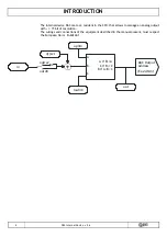
Страница 4: ...CPU that allows to manage an analog output with 15 bit of resolution The wirings and connections of the equipment described in the manual present must respect the European Norm En60204 1 in outrev A A...

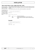
Страница 5: ...evice_name DAC IOutA where device_name Is the name of the device DAC Is the key word that identifies the device analog output IOutA Hardware address of the DAC component of the Slave analog output Exa...

Страница 6: ...offset parameter is a variable which to be added to the in variable in order to adjust the analog output In 32767 10 V maximum analog output value In 0 0V central value of analog output In 32768 10 V...

Страница 7: ...to be considered correct or for the control to be accepted In some cases limit values are specified for the parameter to be accepted however if values external to set limits are introduced the datum i...

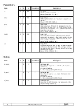
Страница 8: ...will be setted to the Low limit and the st_lowlim status will be activated The value can be positive or negative Range 32768 32767 Bit DAC out W R R Output DAC Simgned analog OOUTPUT of the DAC The v...

Страница 9: ...9 DAC internal device v 2 6 LIMITATIONS Not limitations...

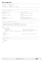
Страница 10: ...empio gestione DAC Release 0 Note 1 Exemple of application for use device DAC Costant definition CONST SYSTEM variables SYSTEM slOutAna L Variable for analog output GLOBAL variables GLOBAL gfCambio F...

Страница 11: ...11 DAC internal device v 2 6 INPUT variables INPUT ifChangeOut F 2 INP01 Change the analog output OUTPUT variables OUTPUT Internal device declaration INTDEVICE Nome Tipe OutAnal Asse DAC 2 AN01 END...

Страница 12: ...na 0 Set analog output input variable to 0 Volt Setting of the analog output Used variables slOutAna percentage value of analog output of uplim ifChangeOut input used to reverse the sign of analog out...

Отзывы: