


68
28 aprile 2021
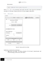
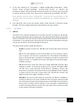
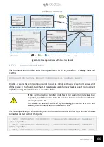
As you can see, the QB Pacer block is used to confront time with the clock of the simulation. The
two times, the clock and the real time, are confronted in a scope. There should be two lines in
it. If the simulation step is set correctly the two lines should be overlapped. If the two lines
diverge, a bigger step size must be set.
In this configuration, the step size is set to 2 milliseconds and the computer should be able to
run it in real time. This means that every 2 milliseconds you send a new reference position to
the qbmove and the current position is read. Furthermore, a current reading is done and you
can see the milliampere absorbed by each of the two motors.
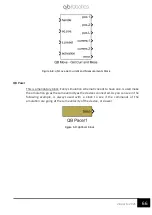
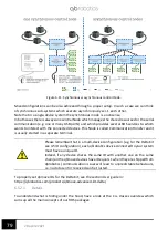
Please remember that in a multi-device configuration (e.g. for the Delta Kit
see 4.5 ID configuration), each qbrobotics device connected to your system
must have a unique ID.
Indeed, if any device shares the same ID with another one on the same
chain (all the qbmove devices have ID equals 1 when they are shipped from
qbrobotics) communication issues will lead to unpredictable behaviors, i.e.
no data sent or received can be trusted.
6.3.3
Delta robot example
When using the ROS packages with a Delta Kit, it is possible to exploit the specific aids provided
by qbrobotics to help in a quicker kinematic structure control.
You can inspect the example by opening the Simulink model:
“/your_working_directory/qbmove_simulink/examples/delta/qbdelta_r2018.slx”
which is valid from MATLAB r2018a on, while `qbdelta_r2017.slx` refers to previous MATLAB
version.
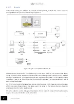
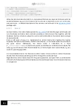
6.3.3.1
Inverse kinematics and control inputs
A specific Delta Kit controller has not been implemented since each single qbmove controller
can be exploited to control the whole system. Anyway, controlling a Delta kinematic structure
only w.r.t. the joint space is not the best option for the end user.
For this reason, we have created the direct and inverse kinematics algorithms which allow a
more user-friendly approach. Without digging too much into the implementation details, which
is publicly available under
“/your_working_directory/qbmove_simulink/examples/delta/”
, the
major improvements are the followings:
•
By exploiting the direct and inverse kinematics of the Delta kinematic structure, the
user can control the end-effector position w.r.t. the cartesian space (cf. the reference
system details in 4.5 ID configuration).
•
The 3D positioning of the end-effector can be more or less compliant to the
surrounding environment by adjusting the stiffness of the three upper joints. This
leads respectively to a less or more precise pursuing of the control reference, but the
compliance can be exploited to achieve many tasks that could not have been done
otherwise.
Содержание qbmove Advanced Kit
Страница 1: ...Please read these instructions before use Do not discard keep for future reference User manual KIT ...
Страница 2: ...www qbrobotics com ...
Страница 14: ...11 28 aprile 2021 Dimensions of the flanges Figure 3 5 C Flange dimensions Figure 3 6 Base flange dimensions ...
Страница 15: ...12 28 aprile 2021 Figure 3 7 Snap on mechanism Figure 3 8 Examples of connection ...
Страница 40: ...37 28 aprile 2021 ...
Страница 63: ...60 28 aprile 2021 IMPORTANT Remember to power the qbmove or the chain before using it ...
Страница 97: ...94 28 aprile 2021 This page was intentionally left blank ...


