


SIEPYEUOQ2A01G AC Drive Q2A Technical Manual
267
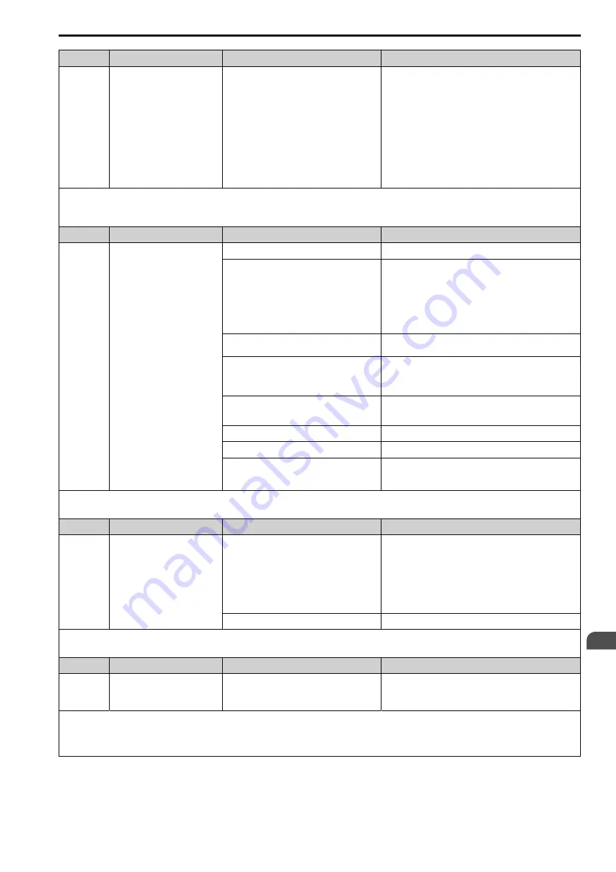
Code
Name
Causes
Possible Solutions
Electrical interference caused a communication data
error.
•
Examine the control circuit lines, main circuit lines, and
ground wiring, and decrease the effects of electrical
interference.
•
Make sure that a magnetic contactor is not the source of the
electrical interference, then use a Surge Protective Device if
necessary.
•
Use only the recommended cables or other shielded line.
Ground the shield on the controller side or the drive input
power side.
•
Isolate the communication wiring from drive power lines, and
install a noise filter to the input side of the power supply for
communication.
•
Decrease the effects of electrical interference from the
controller.
Note:
•
The drive detects this error if it does not correctly receive control data for the
CE
detection time set to
H5-09 [Mbus CE Detect Time]
.
•
Do a Fault Reset to clear the fault.
•
If the drive detects this error, the drive will operate the motor as specified by the stopping method set in
H5-04 [Mbus Error Stop]
.
Code
Name
Causes
Possible Solutions
CF
Control Fault
Motor parameters are set incorrectly.
Correctly set the motor parameters and do Auto-Tuning again.
Drive takes long to ramp to stop when
Control
Method = 4 [Adv OLVector]
because of these
settings:
•
The torque limit is too low.
•
L3-11 = 1 [Overvolt Supression Select =
Enabled]
•
d5-01 = 1 [Torque Ctrl Selection = Torque
Control]
When you have changes in Rotational Auto-Tuning and the
installation environment, make sure that you do Line-to-Line
Resistance Tuning and then set
L8-20 = 1 [CF / STPo Selection =
Disabled]
.
Note:
Do test runs and examine the drive to start and stop correctly
when
L8-20 = 1
.
The torque limit is too low.
Adjust
L7-01 [FW Torque Limit], L7-02 [RV Torque Limit], L7-03
[FW Reg. TrqLimit], and L7-04 [RV Reg. TrqLimit]
.
The load inertia is too big.
•
Adjust
C1-02 [Decel Time 1], C1-04 [Decel Time 2], C1-06
[Decel Time 3], and C1-08 [Decel Time 4
.
•
Set the frequency reference to the minimum output frequency,
and stop the Run command when the drive stops deceleration.
The drive is trying to ramp to stop a machine that
cannot do ramp to stop or on a machine for which
deceleration is not necessary.
Correctly set
b1-03 [Stopping Method Selection]
.
The motor and drive are connected incorrectly.
Correct wiring errors.
Line-to-line Resistance Tuning is not done.
Do Stationary Auto-Tuning for Line-to-Line Resistance.
The drive received a Run command while the motor
was coasting.
•
Examine the sequence and input the Run command after the
motor fully stops.
•
Set
b3-01 = 1 [SpSrch@Start Selection = Enabled]
.
Note:
•
The drive detects this error if the torque reference is more than the torque limit for 3 seconds or longer while the drive ramps to stop.
•
Do a Fault Reset to clear the fault.
Code
Name
Causes
Possible Solutions
CoF
Current Offset Fault
The drive starts operation while the induced voltage
stays in the motor (during coasting to a stop or after
fast deceleration).
•
Make a sequence that does not restart operation when induced
voltage stays in the motor.
•
Set
b3-01 = 1 [SpSrch@Start Selection = Enabled]
.
•
Use
Speed Search from Fmax or Fref [H1-xx = 67, 68]
to do a
speed search through one of the external terminals.
Note:
When controlling the PM motor, External Speed Search
commands 1 and 2 operate the same.
A drive hardware problem occurred.
Replace the drive.
Note:
•
The drive detects this error if the current offset value is more than the permitted setting range while the drive automatically adjusts the current offset.
•
Do a Fault Reset to clear the fault.
Code
Name
Causes
Possible Solutions
CP1
Comparator 1 Limit Fault
The monitor value set in
H2-20 [Compare1 Mon.
Selection]
was within the range of
H2-21
[Compare1 Low Limit]
and
H2-22 [Compare1 Up
Limit]
.
Examine the monitor value and remove the cause of the fault.
Note:
•
The drive detects this error when the terminal is assigned to
H2-01, H2-02, and H2-03 = 3C [Multi-Function Digital Output 1, Multi-Function Digital Output 2, Multi-
Function Digital Output 3 = Comparator1]
.
•
Do a Fault Reset to clear the fault.
•
Set the stopping method for this fault in
H2-33 [Compare1 Protection Selection]
.
Содержание Q2A
Страница 2: ...This Page Intentionally Blank 2 SIEPYEUOQ2A01G AC Drive Q2A Technical Manual...
Страница 12: ...12 SIEPYEUOQ2A01G AC Drive Q2A Technical Manual...
Страница 18: ...i 2 Legal Information 18 SIEPYEUOQ2A01G AC Drive Q2A Technical Manual...
Страница 28: ...1 2 Features and Advantages of Control Methods 28 SIEPYEUOQ2A01G AC Drive Q2A Technical Manual...
Страница 64: ...2 9 Installation Methods 64 SIEPYEUOQ2A01G AC Drive Q2A Technical Manual...
Страница 166: ...4 9 Test Run Checklist 166 SIEPYEUOQ2A01G AC Drive Q2A Technical Manual...
Страница 172: ...5 2 European Standards 172 SIEPYEUOQ2A01G AC Drive Q2A Technical Manual...
Страница 173: ...Standards Compliance 5 5 2 European Standards SIEPYEUOQ2A01G AC Drive Q2A Technical Manual 173...
Страница 174: ...5 2 European Standards 174 SIEPYEUOQ2A01G AC Drive Q2A Technical Manual...
Страница 175: ...Standards Compliance 5 5 2 European Standards SIEPYEUOQ2A01G AC Drive Q2A Technical Manual 175...
Страница 176: ...5 2 European Standards 176 SIEPYEUOQ2A01G AC Drive Q2A Technical Manual...
Страница 258: ...6 2 Modbus Communications 258 SIEPYEUOQ2A01G AC Drive Q2A Technical Manual...
Страница 356: ...8 7 Storage Guidelines 356 SIEPYEUOQ2A01G AC Drive Q2A Technical Manual...
Страница 357: ...SIEPYEUOQ2A01G AC Drive Q2A Technical Manual 357 9 Disposal 9 1 Safety Precautions 358 9 2 Disposal Instructions 359...
Страница 360: ...9 2 Disposal Instructions 360 SIEPYEUOQ2A01G AC Drive Q2A Technical Manual...
Страница 526: ...11 20 Parameters Changed by PM Motor Code Selection 526 SIEPYEUOQ2A01G AC Drive Q2A Technical Manual...


