O p e r a t i O n a n d M a i n t e n a n c e M a n u a l
paGe # 1
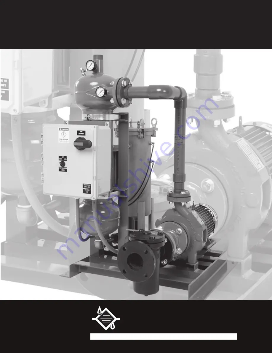
pF-63 Series Separator (ver. 7_10)
OperatiOn and Maintenance Manual
pF-63 Series
Separator
PUROFLUX
FILTRATION AND CONTROL SYSTEMS
C O R P O R A T I O N
Страница 1: ...a t i o n a n d M a i n t e n a n c e M a n u a l PAGE 1 PF 63 Series Separator ver 7_10 Operation and Maintenance Manual PF 63 Series Separator PUROFLUX FILTRATION AND CONTROL SYSTEMS C O R P O R A...
Страница 2: ...ich maintain the separator unit and related equipment If there are any questions on the procedures or performance of the PF 63 series separator contact the local factory representative or call the fac...
Страница 3: ...iping Overview 8 Separator Unit Piping 8 9 Electrical Controls 10 Wiring Requirements 10 CHAPTER 2 Operation and Maintenance 11 Theory of Operation 11 General Maintenance 12 Pump Pre Strainer 13 Pump...
Страница 4: ...ure that all required equipment noted on the bill of lading is received See Figure 1 and Table I for components to be inspected upon receiving Check the model and serial number against the invoice Ser...
Страница 5: ...Standard equipment design is 150 psi 100 F temperature dependent higher design pressures and temperatures are available The PF 63 series separator will remove suspended solids with a specific gravity...
Страница 6: ...The PF 63 series separator should be rigidly anchored to the floor see the specification drawing for location and size of the anchor holes 5 After the PF 63 series separator is installed in its perman...
Страница 7: ...ump designed to maintain proper flows through the separator system Standard units are equipped with a pump to match the required separator system flow gpm 60 feet of head see Table V on page 13 Some i...
Страница 8: ...ed system or slip stream applications as follows 1 Table III on page 9 shows PF 63 series separator piping connections and sizes NOTE Do Not reduce the pipe sizes listed the pipe sizes are minimums If...
Страница 9: ...tion influent line NOTE If the system dynamics dictate a lower or higher discharge pressure the pump motor may require a change to match the actual system dynamics A flow control or throttling device...
Страница 10: ...ncludes a door disconnect switch with overload and short circuit protection Reference Figure 1 on page 4 3 Hand Off Auto Switch HOA is supplied The HOA switch is used to control the pump motor In the...
Страница 11: ...PF 61 series separator collects and concentrates particulate as it falls from the process fluid into the accumulation chamber Because the separator and the accumulation chamber are at equal pressures...
Страница 12: ...ng should not exceed design pressure 3 Clean pump pre strainer check as often as environment dictates 4 Check the gasket condition each time the pre strainer is serviced 5 Check voltage and amperage d...
Страница 13: ...ts the pump wet end is cast iron bronze fitted The close coupled pump and motor assembly is bolted together with hex bolts for ease of maintenance or repair The pump utilizes a standard mechanical sea...
Страница 14: ...low the start up procedures on page 17 whenever the separator unit has been turned off RECOVERY SYSTEM The purged waste from the separator enters the inlet of recovery system and is distributed over t...
Страница 15: ...ct the retaining basket and o ring Remove and clean if necessary Replace retaining basket o ring if needed 8 If the bag is not worn or in need of replacement it can be washed To wash the bag turn it i...
Страница 16: ...ted in the center of the retaining basket plate Secure the hold down ring with the 3 8 nut and washer Do not over tighten the hold down nut 10 Inspect the cover and o ring for foreign matter and clean...
Страница 17: ...electrical power to the separator package must be locked out 3 Check the recovery system by loosening the four bolts holding the cover Inspect the cover o ring for cracks or wear replace it if necessa...
Страница 18: ...and all air has been evacuated the manual air relief valves can be closed Now slowly open the outlet valve on the recovery system 11 Check the voltage and current of all leads on the pump motor The co...
Страница 19: ...7 Remove the drain plug located at the bottom of the recovery vessel Allow the liquid to drain and then replace the drain plug 8 Remove the bolts from the pump pre strainer cover Remove the cover and...
Страница 20: ...oyed by a competent professional Such treatment should be initiated before the system start up and continued regu larly thereafter O p e r a t i o n a n d M a i n t e n a n c e M a n u a l SAFETY All...
Страница 21: ...eplacement of defective parts or product a Return Goods Authorization RGA number must first be obtained from PUROFLUX This will be the record for tracking all items returned to PUROFLUX The RGA form m...
Страница 22: ...C O RP O RATI O N PAGE 22 PF 63 Series Separator ver 7_10 O p e r a t i o n a n d M a i n t e n a n c e M a n u a l P U R O F L U X C O R P O R A T I O N PAGE 20 PF 64 Series Separator ver 3_2_07 FIGU...