Quick start guide to the devices of the E product line
VERSION 1.0
6/14
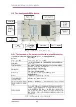
2.2 The front panel of the device
Figure 2-2 The front panel of the device
2.2.1 The structure of the human-machine interface of the device
The E device HMI of the front panel contains the following elements:
Function
Description
16pcs user LEDs
Three-colors, 3mm circular LEDs
COM LED
Yellow, 3mm circular LED indicating EOB communication link
and activity
Touch key LEDs
4pcs yellow, 3mm circular LEDs indicating touch key actions
Device LED
1pc three-colors, 3mm circular LEDs
Green: normal device operation
Yellow: device is in warning state
Red: device is in alarm state
Touch keys
Four capacitive touch keys (On, Off, Page, LED
acknowledgement)
Buzzer
Audible touch key pressure feedback
Changeable LED
description label
Describes user LED functionality
3.5” or optional 5.7” display 320*240 pixels TFT display with resistive touch screen interface
Optical interface for factory
usage
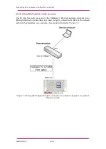
EOB connector
E
thernet
O
ver
B
oard: communication interface accomplishes
isolated, non-galvanic Ethernet connection with the help of a
magnetic attached EOB device. The EOB device has an RJ45
type connector supporting 10Base-T Ethernet connection to the
user computer. This is a proprietary and patented solution from
Protecta ltd.
Table 2-1 The elements of the front panel
COM LED
Change
screen
button
3.5” TFT display
Changeable
LED description
label
User LEDs
Optical
interface
for factory
usage
Touch key LEDs
Device LED
EOB
connector
LED
Reset key
Operation
buttons


