Chapter 3 Hardware Configuration
SP-6150/6155 SERIES USER MANUAL
Page: 3-3
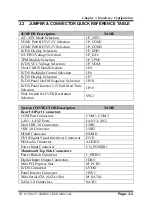
3.2 JUMPER & CONNECTOR QUICK REFERENCE TABLE
JUMPER Description
NAME
AT / ATX Mode Selection
JP_ATX1
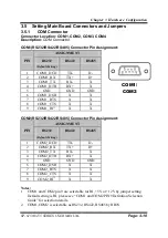
COM1
Pin9
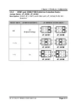
RI/5V/12V Selection
JP_COM1
COM2 Pin9 RI/5V/12V Selection
JP_COM2
LVDS Display Selection
JP_EDP1
I2C PIN2 Voltage Selection
JP_I2C1
TPM Module Selection
JP_TPM1
LVDS VCC Voltage Selection
JP_VDD1
Clear CMOS Data Selection
JP4
LVDS Backlight Control Selection
JP6
LVDS Display Selection
JP7
LVDS Panel On/Off Sequence Selection
JP10
LVDS Panel Inverter 12V Soft-Start Time
Selection
JP10
Slide Switch for LVDS Resolution
Selection
SW2
System CONNECTOR Description
NAME
Rear I/O Port Connectors
COM Port Connectors
COM1, COM2
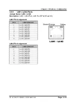
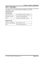
LAN1, LAN2 Ports
LAN1, LAN2
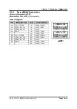
Dual USB 3.0 Connectors
USB1
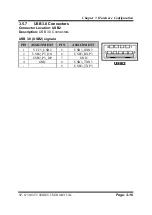
USB 3.0 Connector
USB2
HDMI Connector
HDMI1
DVI (Digital Visual Interface) Connector
DVI1
HD Audio Connector
AUDIO1
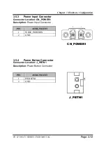
Power Input Connector
CN_POWER1
Mainboard Top Side Connectors
Power Button Connector
J_PBTN1
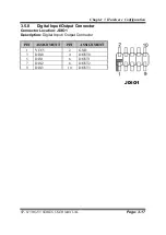
Digital Input/ Output Connectors
JDIO1
Mini PCI Express Slot
M_PCIE1
LVDS Connector
LVDS1
Panel Inverter Connector
JINV1
Mini-Serial ATA (SATA) Slot
M_SATA1
SATA 3.0 Connectors
SATA1
Содержание SP-6150
Страница 9: ...vi Flash BIOS Update B 25...
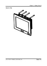
Страница 17: ...Chapter 2 Getting Started SP 6150 6155 SERIES USER MANUAL Page 2 5 Quarter View...
Страница 20: ...Chapter 2 Getting Started SP 6150 6155 SERIES USER MANUAL Page 2 8 Quarter View...
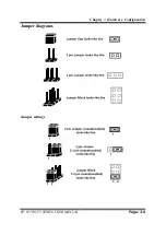
Страница 32: ...Chapter 3 Hardware Configuration SP 6150 6155 SERIES USER MANUAL Page 3 9 Jumper diagrams Jumper settings...
Страница 130: ...Appendix A System Diagrams SP 6150 6155 SERIES USER MANUAL Page A 10 SP 6155 Panel Mount Exploded Diagram...

