Appendix A System Diagrams
SP-6150/6155 SERIES USER MANUAL
Page: A-12
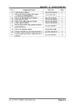
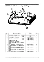
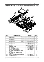
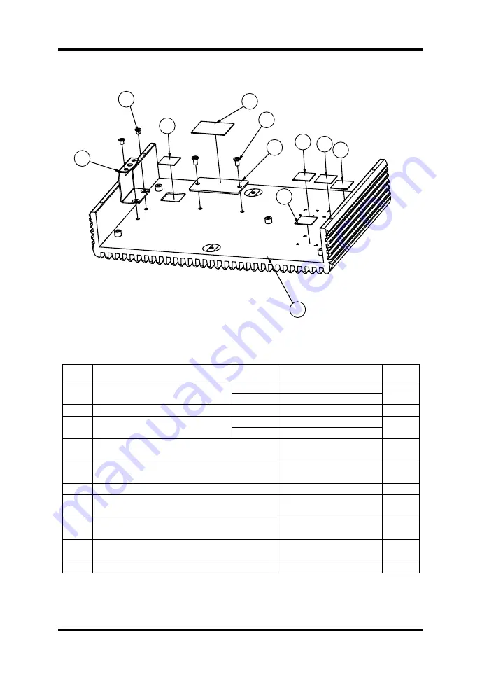
SP-6150 / SP-6155 Heatsink Exploded Diagram
No.
Component Name
P/N No.
Q’ty
1
SE-8134 Heatsink Main Case
Black
N/A
1
Silver
N/A
2
HDD Support Side Braclet
20-006-03002401
1
3
CPU Conduction Block
E3950
81-002-24525001
1
N3350
81-002-24525002
4
Choke Thermal Pads,
K=12,15x15x1.0mm (Gray)
81-006-81515007
1
5
CPU Thermal Pads, K=12,13x13x1mm
(Gray)
81-006-81313003
1
6
Flat Head Screw -- M3(4.0-5.0kg-cm)
22-215-30004011
2
7
LAN Thermal Pads, K=6,10x10x4.0mm
(Red)
81-006-81010005
2
8
Audio Thermal Pads, K=6,7x7x3.5mm
(Red)
81-006-80707001
1
9
PCH Thermal Pads, K=6, 15x15x3.0mm
(Red)
81-006-81515006
1
10
Fillister Head Screw #2 / M3x0.5Px5mm
22-272-30049015
2
01
03
02
06
04
05
10
07 07
08
09
Содержание SP-6150
Страница 9: ...vi Flash BIOS Update B 25...
Страница 17: ...Chapter 2 Getting Started SP 6150 6155 SERIES USER MANUAL Page 2 5 Quarter View...
Страница 20: ...Chapter 2 Getting Started SP 6150 6155 SERIES USER MANUAL Page 2 8 Quarter View...
Страница 32: ...Chapter 3 Hardware Configuration SP 6150 6155 SERIES USER MANUAL Page 3 9 Jumper diagrams Jumper settings...
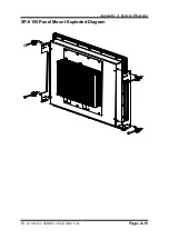
Страница 130: ...Appendix A System Diagrams SP 6150 6155 SERIES USER MANUAL Page A 10 SP 6155 Panel Mount Exploded Diagram...

