background image


Connection with the target circuit

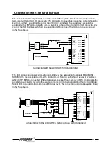
The connection to the target circuit should be realized through the attached 10-lead ribbon cable,
terminated with standard IDC plugs with 2.54 mm raster. In case of using another cable it should be
kept in mind that it should not be longer than 30 cm (~12 inches). The target device should be
equipped with a ISP connector with lead-out identical to that of the programmer ISP connector. We
connect the ISP bus lines with their corresponding ISP bus lines of the microcontroller as shown
in the figure below.


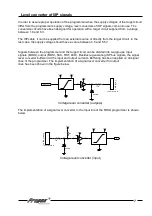
Connection with the 

AT90S8515

 microcontroller

The LED signal can also serve to switching multiplexer the separating the signals MOSI, MISO, 
SCK from the rest of system on time the programming. Solution such should be use in systems in 
which to SPI BUS be connected different arrangements like Flash memory or RTC. It eliminates the 
possibility of accidental record to these arrangements in time the programming the 

microcontroller

Signal LED in programming moment switch to low level. The connection  using multiplexer is shown 
in the figure below.

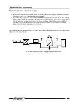
Connection with the 

AT90S8515

 microcontroller with multiplexer


6


1

2

3

4

5

6

A

B

C

D

6

5

4

3

2

1

D

C

B

A

Title

Number

R ev isio n

Size

B

Date:

4-Ju l-20 0 2 

Sheet    o f 

File:

C:\Mo je d ok u men ty \us er\Evb _at90.d d b

Drawn By:

R ESET

9

XTAL2

18

XTAL1

19

GND

20

OC 1B

2 9

ALE

3 0

ICP

3 1

VC C

4 0

PC0 /A8

2 1

PC1 /A9

2 2

PC2 /A1 0

2 3

PC3 /A1 1

2 4

PC4 /A1 2

2 5

PC5 /A1 3

2 6

PC6 /A1 4

2 7

PC7 /A1 5

2 8

PD0/RXD

10

PD1/TXD

11

PD2/INT0

12

PD3/INT1

13

PD4

14

PD5/OC 1 A

15

PD6/W R

16

PD7/R D

17

PB0/T0

1

PB1/T1

2

PB 2/AIN0

3

PB 3/AIN1

4

PB4/SS

5

PB5/MOSI

6

PB6/MISO

7

PB 7/SC K

8

PA0 /AD0

3 9

PA1 /AD1

3 8

PA2 /AD2

3 7

PA3 /AD3

3 6

PA4 /AD4

3 5

PA5 /AD5

3 4

PA6 /AD6

3 3

PA7 /AD7

3 2

AT9 0S851 5

X0

1 2

X1

1 3

Y0

2

Y1

1

Z0

5

Z1

3

INH

6

A

1 1

B

1 0

C

9

X

1 4

Y

1 5

Z

4

4 0 53 /7 4 HC 40 53

PB6

PB7

PB5

1

2

3

4

5

6

7

8

9

1 0

JP2

ISP Head er

RST

ISP ACTIVE

47 0R - 1 k

VTG

VTG

VTG

MOSI
LED

C LK
MISO

Reset circuit

ISP m ultiplexer

1

2

3

4

5

6

A

B

C

D

6

5

4

3

2

1

D

C

B

A

Title

Numb er

R ev isio n

Size

B

Date:

4 -Jul-20 0 2  

Sh eet    of 

File:

C:\Moje dok umen ty \us er\Ev b_at9 0.dd b

Drawn  By :

R ESET

9

XTAL2

1 8

XTAL1

1 9

GND

2 0

OC 1 B

29

ALE

30

ICP

31

VC C

40

PC0 /A8

21

PC1 /A9

22

PC2 /A1 0

23

PC3 /A1 1

24

PC4 /A1 2

25

PC5 /A1 3

26

PC6 /A1 4

27

PC7 /A1 5

28

PD0 /RXD

1 0

PD1 /TXD

1 1

PD2 /INT0

1 2

PD3 /INT1

1 3

PD4

1 4

PD5 /OC 1A

1 5

PD6/W R

1 6

PD7/R D

1 7

PB0 /T0

1

PB1 /T1

2

PB 2 /AIN0

3

PB 3 /AIN1

4

PB4 /SS

5

PB5 /MOSI

6

PB6 /MISO

7

PB 7 /SC K

8

PA0 /AD0

39

PA1 /AD1

38

PA2 /AD2

37

PA3 /AD3

36

PA4 /AD4

35

PA5 /AD5

34

PA6 /AD6

33

PA7 /AD7

32

AT9 0 S85 15

1

2

3

4

5

6

7

8

9

10

JP2

ISP Head er

RST

ISP ACTIVE

47 0 R - 1 k

VTG

VTG

VTG

MOSI
LED

C LK
MISO

Reset circuit

Содержание ISPcable II

Страница 1: ...uation Boards for ethernet controllers RFID H igh nim odules for m icrocontrollers Servers Prototyping Boards m i lers Starter Kits Em bedded W eb 51 AVR ST PIC m icrocontrol Speed In System s program m e rocontrollers Starter Kits Em be ards for 51 AVR ST PIC m ic PC B designing Evaluation Bo ollers M icroprocesor system s rs for AVR PIC ST m icrocontrl dded W eb Serw ers Prototyping m ers for AV...

Страница 2: ...tudio AVR Prog not all microcontorllers software from Atmel as well Moreover functions offered by ProProgRS are available such as programming and read out of Flash memories EEPROM fuse and lock bits RESET signal configuration SPI frequency Due to the small size it is also an excellent tool for field upgrades of existing applications Let us wish you nothing but success and a lot of satisfaction in ...

Страница 3: ...ree software upgrade Extensive embedded help Supported devices Below is a list of devices supported by the programmer As new devices appear the list is going to be modified AT89S tinyAVR AVR megaAVR AT89S8252 AT89S8253 AT89S51 AT89S52 AT89S53 ATtiny12 ATtiny13 ATtiny15 ATtiny22 ATtiny26 ATtiny2313 AT90S1200 AT90S2313 AT90S2323 AT90S2333 AT90S2343 AT90S4414 AT90S4433 AT90S4434 AT90S8515 AT90S8534 A...

Страница 4: ...TBD TBD TBD TBD TBD TBD ATmega103 1 TBD TBD TBD TBD TBD TBD ATmega323 8 TBD TBD TBD TBD TBD TBD ATmega323 1 TBD TBD TBD TBD TBD TBD ATmega128 16 TBD TBD TBD TBD TBD TBD ATmega128 1 TBD TBD TBD TBD TBD TBD Note The only minimum times of programming in schedule were passe for some devices TBD the times be become passed in next version of this users guaid Description of the programmer Power External ...

Страница 5: ...the target circuit in the Atmel standard 5 OPIS WYPROWADZEŃ MOSI SPI sygnał danych Master wy Slave we LED LED diode and multiplexer signal RST Target RESET control pin SCK SPI serial clock signal MISO SPI data signal Master in Slave out VCC Power supply from target circuit 1 5 6V GND Programmer ground ...

Страница 6: ... figure below Connection with the AT90S8515 microcontroller with multiplexer 6 4 3 2 1 D C B R ESET 9 XTAL2 18 XTAL1 19 GND 20 OC 1B 29 ALE 30 ICP 31 VC C 40 PC0 A8 21 PC1 A9 22 PC2 A10 23 PC3 A11 24 PC4 A12 25 PC5 A13 26 PC6 A14 27 PC7 A15 28 PD0 RXD 10 PD1 TXD 11 PD2 INT0 12 PD3 INT1 13 PD4 14 PD5 OC 1A 15 PD6 W R 16 PD7 R D 17 PB0 T0 1 PB1 T1 2 PB 2 AIN0 3 PB 3 AIN1 4 PB4 SS 5 PB5 MOSI 6 PB6 MI...

Страница 7: ... Signals between the programmer and the target circuit can be divided into two groups input signals MISO output MOSI SCK RST LED Besides regenerating ISP bus signals the signal level converter buffers limit the input and output currents Buffering has been applied on all signal lines of the programmer The implementation of a signal level converter for output lines has been shown in the figure below...

Страница 8: ...r closing power jumper power to the target circuit can be supplied the maximum current is 50 mA However power supply programmer unit should be done across connector about diameter of pin 2 5 mm The Voltage should be since 9 to 15V for DC and since 7 to 13 for AC The implementation of arrangement of the power supply inside the programmer unit ISPcable II was showed on following drawing Arrangement ...

Страница 9: ...rnal power supply Vpower 7 12 DC 6 15 AC Ip max 50mA VTG 1 8 6 0V Is max 5mA Contents of delivery package ICPcable II programmer RS232 cable for connection of the emulator with a PC Cable terminated with IDC 10 plugs for connection of the programmer with the target circuit CD with documentation and software Technical assistance In order to obtain technical assistance please contact support propox ...

Отзывы: