October 2021
75
Chapter 4: RF SIGNAL TUNING
►
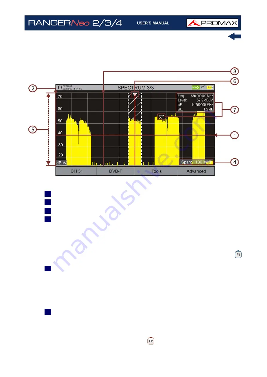
FULL SPECTRUM (SPECTRUM 3/3) WITH MARKER
Figure 54.
1
Horizontal reference line: It shows level of signal.
2
Vertical axis: It indicates the signal level.
3
Vertical reference line: It indicates the frequency.
4
SPAN: It is the frequency range displayed on the horizontal axis. Span values
available changes according to Resolution Bandwidth selected. The current
span value appears at the bottom right of the screen. To switch among span
default values use the joystick (left, right) in span mode (SP). For example,
for RBW = 100 kHz default span values are Full (full band), 500 MHz, 200
MHz, 100 MHz, 50 MHz, 20 MHz and 10 MHz. To change to any other span
value in that frequency range use the "span" option in the Tuning menu (
key).
5
Reference Level: It is the power range represented on the vertical axis. To
change use the joystick (up, down; 5 dB steps). This equipment has an option
to activate the automatic adjustment of the reference level, so it detects the
optimal reference level for each situation.
In automatic mode, it sets the
optimum reference level each time it enters the spectrum mode. This option
can be enabled or disabled through the
PREFERENCES
menu and
Measurements
tab.
6
Cursor: Red vertical line that indicates position during the channel or
frequency tuning. When a digital signal is detected, there is a triple cursor
that shows the frequency for the signal locked and two vertical lines that
shows the bandwidth of the digital carrier. In the case of a GENERIC signal,
the bandwidth shown is the one selected by the user on the "Signal
Parameters" menu when pressing the
key. To change frequency/channel
Содержание RANGER Neo 2
Страница 1: ...RANGER Neo 2 TV AND SATELLITE ANALYZER 0 MI2130 RANGER Neo 3 RANGER Neo 4 ...
Страница 20: ...Chapter 2 SETTING UP 8 October 2021 Figure 4 Side View ...
Страница 21: ...October 2021 9 Chapter 2 SETTING UP Figure 5 Top View ...
Страница 22: ...Chapter 2 SETTING UP 10 October 2021 Figure 6 Front View For Optical Option refer to annex 2 3 2 RANGER Neo 3 ...
Страница 23: ...October 2021 11 Chapter 2 SETTING UP Figure 7 Side View ...
Страница 24: ...Chapter 2 SETTING UP 12 October 2021 Figure 8 Top View ...
Страница 25: ...October 2021 13 Chapter 2 SETTING UP Figure 9 Front View For Optical Option refer to annex 2 3 3 RANGER Neo 4 ...
Страница 26: ...Chapter 2 SETTING UP 14 October 2021 Figure 10 Side View ...
Страница 27: ...October 2021 15 Chapter 2 SETTING UP Figure 11 Top View ...
Страница 30: ...Chapter 2 SETTING UP 18 October 2021 RF Menu Figure 13 RF Tuning 2 7 Menu Tree ...
Страница 31: ...October 2021 19 Chapter 2 SETTING UP Figure 14 Tools Menu ...
Страница 32: ...Chapter 2 SETTING UP 20 October 2021 Figure 15 Advanced Menu ...
Страница 33: ...October 2021 21 Chapter 2 SETTING UP WiFi Menu Figure 16 ...
Страница 34: ...Chapter 2 SETTING UP 22 October 2021 IPTV Menu Figure 17 Figure 18 ...
Страница 35: ...October 2021 23 Chapter 2 SETTING UP Installation Management Menu Figure 19 ...
Страница 36: ...Chapter 2 SETTING UP 24 October 2021 Preferences Menu Figure 20 ...
Страница 37: ...October 2021 25 Chapter 2 SETTING UP Settings Menu Figure 21 Figure 22 ...
Страница 101: ...October 2021 89 Chapter 4 RF SIGNAL TUNING Figure 68 DAB Spectrum 2 3 Figure 69 DAB Spectrum 3 3 ...
Страница 102: ...Chapter 4 RF SIGNAL TUNING 90 October 2021 Figure 70 DAB 1 3 Figure 71 DAB 2 3 4 6 4 5 TV Mode ...
Страница 259: ...October 2021 247 Chapter 10 WEBCONTROL Figure 162 Spectrum Graph Monitoring Deviation Detection ...
Страница 303: ...October 2021 291 Chapter i OPTICAL OPTION Figure 174 Auxiliary Input Signal Selection Figure 175 Band Selection ...
Страница 336: ...Chapter v RACK OPTION 324 October 2021 Figure 200 Side View Figure 201 Back View ...


