Produal HLS 44 Скачать руководство пользователя страница 1

USER GUIDE

HLS 44

V2.0 (08.03.2012) 


1 (20) 


Produal Oy 

Keltakalliontie 18, 48770 Kotka FINLAND 

Tel: +358-5-230 9200 / Fax: +358-5-230 9210 

[email protected] 

www.produal.com 

This user guide is for controllers with the software version 1.1.0, 1.1.1 or 1.1.2. 

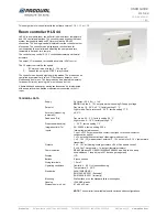
Room controller HLS 44 

HLS 44 is a versatile room controller for individual room temperature 
and VAV control applications. The controller can be connected to any 
system that supports Modbus RTU protocol via the RS-485 
connection. The bus is galvanically isolated from the controller's other 
electronics. The controller has a display and touch buttons for 
commissioning the controller and adjusting the user parameters, 
temperature set point, for example. 

The controller can control 0...10 V controlled actuators and thermal 
actuators. 

The output Y1 is reserved for variable air volume (VAV) control. 

The Y2 output controls the fan speed: 

1. 

EC motor: directly with the 0…10 V signal 

2. 

3-speed fan: using the FCRY 3 relay module 

The controller has day and night operating modes. The modes can be 
controlled by external card switch, PIR occupancy detector, over 
Modbus and from menu. The day mode can be activated temporarily 
for a specific time by touching the "man in house" button. 

A demand based and energy saving ventilation can be implemented 
with a separate carbon dioxide measurement connected to the U1 
input.  


TECHNICAL DATA 


Supply 

24 Vac/dc (20…28 V), < 1 VA 

NOTE:

 Only the 0…10 V outputs work when using DC supply voltage.


Set point 

Day mode: 18…26 °C, ±3 °C, factory setting 21 °C 
Night mode: Frost protection 8…50 °C, factory setting 17 °C 


Accuracy (measuring 
inaccuracy) 

±0.5 °C 


Dead zone (Dz) 

Day mode: 0.2...3 °C, factory setting 0.2 °C 
Night mode: 0…10 °C, factory setting 6 °C 


Proportional band (Xp) 

1…32 °C, factory setting 1 °C 


Integration time (Tn) 

50…50000 s, factory setting 300 s 


Inputs 

Internal temperature sensor 
1 x ext. NTC10 or potential-free contact input (door or window contact or 
condensation switch) 
1 x DI, potential-free contact input (day/night mode control) 
1 x 0...10 V (CO

measurement, external 0...10 V set point or 0...10 V temperature 

transmitter) 

 Outputs 


4 x 0...10 Vdc (Heating/cooling actuators, VAV or Fan speed control) 
2 x 24 Vac Triac outputs, < 1 A/output (thermal actuators) 


Communication 

RS-485 Modbus RTU, 9600/19200/38400/56000 bps, 8 data bits, parity 
none/odd/even,1 stop bit (up to 247 devices per segment) 

 Display 

LCD 


Buttons 

4 touch buttons 


Wiring terminals 

1.5 mm

2


 Operating 

conditions 

Humidity: 0…85 % rH non-condensing 
Temperature: 0…50 ºC 

 Standards 

2004/108/EY(EMC) 
EN61000-6-3: 2001 (Emission) 
EN61000-6-2: 2001 (Immunity) 


Mounting 

Wall surface or on the standard flush mounting box  


Housing 

IP20, ABS plastic 


Dimensions (w x h x d) 

87 x 86 x 32 mm 


NOTE:

 The controller is available also with various button configurations. 

Содержание HLS 44

Страница 1: ...mented with a separate carbon dioxide measurement connected to the U1 input TECHNICAL DATA Supply 24 Vac dc 20 28 V 1 VA NOTE Only the 0 10 V outputs work when using DC supply voltage Set point Day mo...

Страница 2: ...al current consumption must not exceed 1 A The triac outputs are protected with fuses that can only be changed by the manufacturer NOTE Unused inputs and outputs can also be used for transferring othe...

Страница 3: ...ontroller buttons or by using the HLS 44 SER commissioning tool The commissioning tool settings can be loaded to the controller or the controller settings can be loaded to the configuration tool and t...

Страница 4: ...produal fi www produal com MENU Menu is activated by setting the configuration mode selector to the closed position You can proceed in the menu by touching the and buttons The values can be changed wi...

Страница 5: ...Eq Sequence of cooling stages Valve FAN Fan usage 3 Heating and 1 stage cooling valve opens before the fan speed increases Parameter Description choose Cramp Cooling stages 1St Fan Fan stage simultane...

Страница 6: ...Thermal actuator x x Note the following parameters Parameter Modbus register Description factory setting Min Max Cramp 17 Cooling stages 1St 1St 2St 1St 1 stage 2St 2 stages MJAM 22 Valve jam preventi...

Страница 7: ...n speed 3 is allowed in the automatic mode Fan control The fan can be 3 speed or 0 10 V controlled EC motor In the manual mode the EC motor works so that the switch position is 0 0 1 33 2 66 and 3 100...

Страница 8: ...sensor is not available if the 0 10 V transmitter is selected CO2LO 40039 Low limit P band for CO2control 700 400 1000 Low limit P band for CO2control CO2HI 40040 High limit P band for CO2control 125...

Страница 9: ...t DI1 U1 S DI2 Output Y1 Y2 A1 A2 Y3 Y4 Thermal actuator x x VAV x FAN x Note the following parameters Parameter Modbus register Description factory setting Min Max EXT S 40009 External temperature se...

Страница 10: ...al can be connected to the DI1 or DI2 input and the signal can then be read via the Modbus DI input must be set to not in use position DI1mod 0 or EXT S OFF Input DI1 U1 S DI2 Output Y1 Y2 A1 A2 Y3 Y4...

Страница 11: ...AL INPUT DI2 input can be used to control the controller by using a door window contact or dew point guard with relay output In the door window contact case the controller prevents cooling and heating...

Страница 12: ...ax EXT S 40009 External temperature sensor DI2 contact input OFF OFF 3 OFF not in use 1 external NTC sensor 2 DI2 door window contact prevents both heating and cooling 3 DI2 condensation switch preven...

Страница 13: ...ht dead zone The night dead zone is defined with the NDZ C parameter Day mode Night mode Note the following parameters Parameter Modbus register Description factory setting Min Max EXT S 40009 Externa...

Страница 14: ...mperature rises 2 C over the set point FG C parameter the heating valve closes and the fan stops The procedure repeats until the controller moves to day mode Day Night Note the following parameters Pa...

Страница 15: ...asurement with NTC10 sensor EXT S parameter is 1 3 External 0 10 V temperature measurement U1mod parameter is 3 NOTE The external 0 10 V temperature transmitter range must be 0 50 C The set point can...

Страница 16: ...000 0 10 00 V 30013 Cooling control connector Signed 16 0 1000 0 10 00 V 30014 Heating control connector Signed 16 0 1000 0 10 00 V Holding registers Register Parameter description Data Type Value Ran...

Страница 17: ...rs the Modbus register SERVICE ALARM bit changes to ON position The alarm is for information purposes only and does not affect to the controller functions The alarm can be reset via the Modbus NETWORK...

Страница 18: ...t Off 0 On 1 Off On 0 8 Light control overdrive enable B2 Bit Off 0 On 1 Off On 0 9 Overdrive On off damper by Modbus B1 Bit Off 0 On 1 Off On 0 10 Overdrive Light control by Modbus B2 Bit Off 0 On 1...

Страница 19: ...ntroller Signed 16 0 4 0 1 2 3 4 30011 FAN speed connector Signed 16 0 1000 0 10 00 V 30012 VAV control connector Signed 16 0 1000 0 10 00 V 30013 Cooling control connector Signed 16 0 1000 0 10 00 V...

Страница 20: ...ive Signed 16 0 60 0 60 min 0 40024 DI1 delay active to passive Signed 16 0 60 0 60 min 5 40025 Duration of temporary day mode Signed 16 1 480 1 480 min 120 40026 Minimum VAV output in day mode Signed...

Отзывы: