background image

11

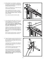
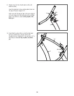
12.

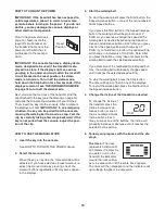
Be careful not to pinch the wires in the Right

Handrail (105).

Attach the console assembly to the Right

Handrail (105) with two #8 x 3/4" Screws (1) and

a 1/4" x 1 1/4" Bolt (6) with a 1/4" Star Washer

(10).

Repeat this step on the left side of the

console assembly. Start all four Screws and

both Bolts before tightening any of them.

See steps 5 and 7–10. Tighten all of the bolts

used in these assembly steps.

1

10

6

Console Assembly

105

12

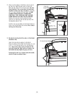
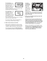
11. Have a second person hold the console assem-

bly near the Right Upright (79). Connect the

Wire Harness (86) to the console wire.

See the

inset drawing. The connectors should slide

together easily and snap into place.

If they do

not, turn one connector and try again.

IF THE

CONNECTORS ARE NOT CONNECTED

PROPERLY, THE CONSOLE MAY BE DAM-

AGED WHEN YOU TURN ON THE POWER.

Remove the wire tie from the Wire Harness.

Insert the connectors and the excess wire into

the Right Handrail (105).

Set the console assembly on the Right Handrail

(105) and Left Handrail (not shown).

Be careful

not to pinch the wires.

79

Console

Assembly

11

86

Console

Wire

Wire Tie

105

Console

Wire

86

Содержание 780 Zlt Treadmill

Страница 1: ...l for future reference QUESTIONS If you have questions or if there are missing parts please contact us Call 08457 089 009 From Ireland 053 92 36102 E mail www iconsupport eu Write ICON Health Fitness Ltd c o HI Group PLC Express Way Whitwood West Yorkshire WF10 5QJ UK Write the serial number in the space above for reference USER S MANUAL www iconeurope com ...

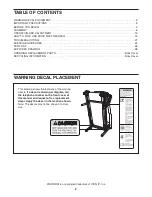
Страница 2: ...DRAWING 28 ORDERING REPLACEMENT PARTS Back Cover RECYCLING INFORMATION Back Cover PROFORM is a registered trademark of ICON IP Inc This drawing shows the locations of the warning decals If a decal is missing or illegible call the telephone number on the front cover of this manual and request a free replacement decal Apply the decal in the location shown Note The decals may not be shown at actual s...

Страница 3: ...the fuse an ASTA approved BS1362 type should be fitted to the fuse carrier A 13 amp fuse should be used 12 If an extension cord is needed use only a 3 conductor 1 mm2 14 gauge cord that is no longer than 1 5 m 13 Keep the power cord and the surge suppres sor away from heated surfaces 14 Never move the walking belt while the power is turned off Do not operate the treadmill if the power cord or plug...

Страница 4: ...arly 24 DANGER Always unplug the power cord immediately after use before cleaning the treadmill and before performing the mainte nance and adjustment procedures described in this manual Never remove the motor hood un less instructed to do so by an authorized ser vice representative Servicing other than the procedures in this manual should be performed by an authorized service representative only 2...

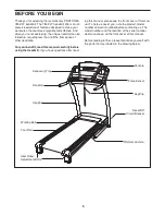
Страница 5: ...using the treadmill If you have questions after read ing this manual please see the front cover of this man ual To help us assist you note the product model number and serial number before contacting us The model number and the location of the serial number decal are shown on the front cover of this manual Before reading further please familiarize yourself with the parts that are labeled in the dr...

Страница 6: ...nd your own Phillips screwdriver adjustable wrench needlenose pliers scissors and rubber mallet Use the drawings below to identify the assembly hardware The number in parentheses below each drawing is the key number of the part from the PART LIST near the end of this manual The number after the parentheses is the quantity needed for assembly Note If a part is not in the hardware kit check to see i...

Страница 7: ... steps 3 and 6 60 11 C 1 3 2 With the help of a second person carefully tip the treadmill onto its left side Partially fold the Frame 53 so that the treadmill is more stable do not fully fold the Frame yet Remove and discard the two indicated bolts A and the shipping bracket B Cut the tie securing the Wire Harness 86 to the Base 60 Locate a tie in the indicated hole in the Base and use the tie to ...

Страница 8: ...f the Bolts touch the Right Upright do not fully tighten the Bolts yet 83 79 86 12 84 5 5 4 Identify the Right Upright 79 and the Right Upright Spacer 83 Insert the Wire Harness 86 through the Right Upright Spacer as shown Set the Right Upright Spacer on the Base 60 With the help of a second person hold the Right Upright 79 near the Base 60 See the inset drawing Tie the wire tie in the Right Uprig...

Страница 9: ...ble do not fully fold the Frame yet Remove and discard the two indicated bolts A and the shipping bracket B Attach a Wheel 90 with the 3 8 x 2 Bolt 3 and the 3 8 Locknut 11 that you removed in step 1 Do not overtighten the Nut the Wheel must turn freely Press a Base Cap 85 into the Base 60 6 90 53 3 B A 85 11 8 Identify the Right Handrail 105 Remove the tie from the bracket on the Right Handrail H...

Страница 10: ...eft Handrail 106 to the Left Upright 77 with three 5 16 Star Washers 9 and three 5 16 x 3 4 Bolts 4 do not fully tighten the Bolts yet 4 4 9 106 77 9 10 Orient the Crossbar 78 so that the indicated bump is positioned as shown Attach the Crossbar to the Uprights 77 79 with four 1 4 x 5 8 Bolts 7 do not fully tighten the Bolts yet 77 79 78 Bump 7 7 10 Tie ...

Страница 11: ...econd person hold the console assem bly near the Right Upright 79 Connect the Wire Harness 86 to the console wire See the inset drawing The connectors should slide together easily and snap into place If they do not turn one connector and try again IF THE CONNECTORS ARE NOT CONNECTED PROPERLY THE CONSOLE MAY BE DAM AGED WHEN YOU TURN ON THE POWER Remove the wire tie from the Wire Harness Insert the...

Страница 12: ...the Latch Knob 51 are in the posi tions shown Remove the tie from the upper end of the Storage Latch 50 Attach the upper end of the Storage Latch to the bracket on the Frame 53 with a 3 8 x 2 Bolt 3 and a 3 8 Locknut 11 Remove the tie from the lower end of the Storage Latch 50 Keep the holes in the Latch Cap 49 aligned with the holes in the Storage Latch Make sure to keep the Latch Cap in side the...

Страница 13: ...l See drawing 2 Press the pins on the power cord into the metal clips in the adapter as shown Close the adapter cover over the end of the power cord and tighten the screw in the adapter IMPORTANT Make sure that the adapter cover is secure and the screw has been tightened before using the power cord See drawing 3 Plug the power cord into an appropriate outlet that is properly installed and earthed ...

Страница 14: ...isten to your favorite workout music or audio books with the consoleʼs premium stereo sound system while you get in shape To turn on the power see page 15 To use the man ual mode see page 15 To use a preset workout see page 17 To use the stereo sound system see page 18 To use the information mode see page 18 IMPORTANT If there is a sheet of clear plastic on the face of the console remove the plast...

Страница 15: ...ut re select the manual mode by pressing one of the workout buttons repeatedly until only zeros appear in the displays 3 Start the walking belt To start the walking belt press the Start button the Speed increase button or one of the ten numbered Quick Speed buttons If you press the Start button or the Speed increase button the walking belt will begin to move at 2 Km H As you exercise change the sp...

Страница 16: ...asure your heart rate stand on the foot rails and hold the contacts for approximately 10 seconds avoid moving your hands When your pulse is de tected one or two dashes will appear in the display and then your heart rate will be shown For the most accurate heart rate reading continue to hold the contacts for about 15 seconds 7 When you are finished exercising remove the key from the console Step on...

Страница 17: ...s of tones will sound and the next segment of the profile will begin to flash If a different speed or incline setting is programmed for the next segment the speed or incline setting will appear in the display to alert you The workout will continue in this way until the last segment of the profile flashes in the display and the last segment ends The walking belt will then slow to a stop If the spee...

Страница 18: ... while holding down the Stop button Then re lease the Stop button When the information mode is selected the following information will be shown The left display will show the total number of hours that the treadmill has been used The right display will show the total number of kilome ters or miles that the walking belt has moved Press the Stop button again to view the following infor mation An M f...

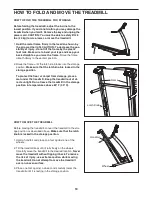
Страница 19: ... the latch knob is locked in the storage position To protect the floor or carpet from damage place a mat under the treadmill Keep the treadmill out of di rect sunlight Do not leave the treadmill in the storage position in temperatures above 85 F 30 C HOW TO MOVE THE TREADMILL Before moving the treadmill convert the treadmill to the stor age position as described above Make sure that the latch knob...

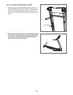
Страница 20: ...It may be neces sary to push the frame forward as you pull the knob to the left Pivot the frame downward and release the latch knob 2 Hold the metal frame firmly with both hands and lower it to the floor CAUTION Do not grip only the plastic foot rails or drop the frame to the floor Bend your legs and keep your back straight Latch Knob Frame ...

Страница 21: ...five minutes and then press the switch back in b Make sure that the power cord is plugged in If the power cord is plugged in unplug it wait for five minutes and then plug it back in c Remove the key from the console Reinsert the key into the console d If the treadmill still will not run please see the front cover of this manual PROBLEM The console displays remain lit when you remove the key from t...

Страница 22: ...treadmill will automatically rise to the maximum incline level and then return to the minimum level This will recalibrate the incline system PROBLEM The walking belt slows when walked on SOLUTION a If an extension cord is needed use only a 3 conductor 14 gauge 1 mm2 cord that is no longer than 5 ft 1 5 m b If the walking belt is overtightened treadmill perfor mance may decrease and the walking bel...

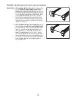
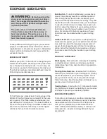
Страница 23: ...in the power cord insert the key and run the treadmill for a few minutes Repeat until the walk ing belt is centered b If the walking belt slips when walked on first re move the key and UNPLUG THE POWER CORD Using the hex key turn both idler roller bolts clock wise 1 4 of a turn When the walking belt is cor rectly tightened you should be able to lift each edge of the walking belt 2 to 3 in 5 to 7 c...

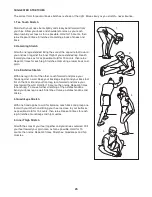
Страница 24: ... goal is to strengthen your cardiovascular system you must perform aerobic exer cise which is activity that requires large amounts of oxygen for prolonged periods of time For aerobic ex ercise adjust the intensity of your exercise until your heart rate is near the highest number in your training zone WORKOUT GUIDELINES Warming Up Start with 5 to 10 minutes of stretching and light exercise A warm u...

Страница 25: ...illes Stretch With one leg in front of the other reach forward and place your hands against a wall Keep your back leg straight and your back foot flat on the floor Bend your front leg lean forward and move your hips toward the wall Hold for 15 counts then relax Repeat 3 times for each leg To cause further stretching of the achilles tendons bend your back leg as well Stretches Calves achilles tendo...

Страница 26: ...40 2 Platform Cushion 41 1 Walking Platform 42 1 Walking Belt 43 2 Belt Guide 44 2 Frame Cap 45 2 Frame Spacer 46 1 1 4 x 1 Bolt 47 1 Drive Roller Pulley 48 1 Magnet 49 1 Latch Cap 50 1 Storage Latch 51 1 Latch Knob 52 1 Right Foot Rail 53 1 Frame 54 2 Roller Bracket 55 1 Idler Roller Ground Wire 56 1 Right Rear Foot Insert 57 1 Right Rear Foot 58 1 Left Rear Foot Insert 59 1 Left Rear Foot 60 1 B...

Страница 27: ... Key Switch 112 2 Motor Isolator 113 1 Motor Plate 114 1 Electronics Plate 115 1 Filter 116 1 Transformer 117 1 Receptacle 8 Blue Wire 2F 10 Blue Wire 2F 4 Red Wire M F 4 Black Wire 2F 4 Green Wire w Decal 8 White Wire 2F 4 Black Wire M F 8 Green Yellow Wire F R Userʼs Manual Note Specifications are subject to change without notice See the back cover of this manual for information about ordering r...

Страница 28: ...9 19 29 28 29 28 57 59 23 23 27 27 43 43 25 25 25 44 25 25 25 25 25 38 37 32 32 32 48 44 45 32 40 41 39 42 47 52 38 61 40 53 54 54 45 56 58 36 35 34 34 14 49 14 55 16 16 11 109 46 28 EXPLODED DRAWING A Model No PETL81708 2 R0809A ...

Страница 29: ...3 13 13 13 69 16 68 33 33 33 1 1 1 18 18 23 71 67 66 63 64 76 70 65 24 23 62 23 75 24 24 26 112 113 73 72 117 114 74 115 116 23 23 23 23 108 108 101 100 EXPLODED DRAWING B Model No PETL81708 2 R0809A 29 ...

Страница 30: ...88 3 90 11 11 90 3 5 12 5 12 4 9 4 22 22 31 31 85 85 77 79 60 87 82 83 93 91 84 84 89 21 20 31 81 80 86 92 86 9 4 9 4 9 4 7 7 7 78 7 2 31 2 2 87 9 88 89 2 15 30 EXPLODED DRAWING C Model No PETL81708 2 R0809A ...

Страница 31: ...110 111 30 106 103 1 107 14 99 94 97 96 1 1 1 95 1 98 104 105 104 1 6 10 14 10 6 1 1 1 110 1 102 104 104 30 110 110 110 23 31 EXPLODED DRAWING D Model No PETL81708 2 R0809A ...

Страница 32: ...part s see the PART LIST and the EXPLODED DRAWING near the end of this manual RECYCLING INFORMATION This electronic product must not be disposed of in municipal waste To preserve the environment this product must be recycled after its useful life as required by law Please use recycling facilities that are authorized to collect this type of waste in your area In doing so you will help to conserve n...

Отзывы: