background image

FP-3710K Series User Manual

5-2

5.1

Installation

5.1.1

Installation Procedures

Follow the steps given below when installing the FP.

„

Check the Installation Gasket’s Seating

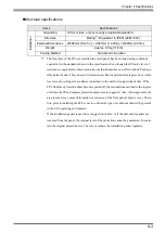
It is strongly recommended that you use the installation gasket, since it absorbs vibration in addition to 

repelling water.

Place the FP on a level surface with the display panel facing downward. Check that the FP’s installation 

gasket is seated securely into the gasket’s groove, which runs around the perimeter of the panel’s frame.

For details about installing the gasket, refer to     

SEE

10.1.2 Replacing the Installation Gasket (page10-3)

• Before installing the FP into a cabinet or panel, check that the installation gasket 

is securely attached to the unit.

• A gasket which has been used for a long period of time may have scratches or 

dirt on it, and can lose much of its dust and drip resistance. Be sure to change the 

gasket periodically (or when scratches or dirt become visible).

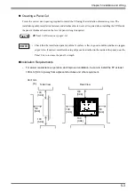
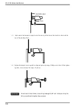
• Be sure the gasket’s seam is not inserted into any of the unit’s corners, only in the 

straight sections of the groove. Inserting it into a corner may lead to its eventually 

tearing.

• To ensure the installation gasket’s maximum level of moisture resistance, be sure 

the gasket’s seam is inserted as shown into the panel’s bottom face.

Rear face

Gasket

Содержание FP-3710K Series

Страница 1: ...3 6HULHV 8VHU 0DQXDO...

Страница 2: ...ics Corporation All rights reserved NOTICE 1 Copying this manual s contents either in whole or in part is prohibited without the express permission of Digital Electronics Corporation Japan 2 The infor...

Страница 3: ...sent danger of electrical shock be sure to unplug the power cable from the FP unit before plugging the cable s other end into the wall Do not use power in excess of the unit s specified voltage range...

Страница 4: ...ructions given in Chapter 3 Installation and Wiring to insure it is done correctly Do not use the FP in an environment with flammable gas since it may cause an explosion The FP is not appropriate for...

Страница 5: ...viewed from an angle outside the specified view angle This is also normal Displaying a single screen image for long periods of time can cause an afterimage to remain To correct this turn the unit OFF...

Страница 6: ...lity that the new board may not be able to be connected to the FP Series Full Resolution FP 3710K Series 1024 768 SEE 4 1 3 Interface Specifications page4 5 When a signal timing value not compatible w...

Страница 7: ...to ensure the safe operation of the FP Contains additional or useful information 1 2 Indicates steps used to accomplish a given task Be sure to follow these steps in the order they are written 1 Indi...

Страница 8: ...stallation Gasket Installation Fasteners attached to the FP unit 1 4 fasteners per set 3 sets AC Power Connector USB Cable Clamp 1 attached to the FP unit 1 Warning Caution Information 1 This unit has...

Страница 9: ...f standard Even without its optional protective cover the front panel is highly resistant to both water and dust Panel can be used as a VGA Display Since the FP is equipped with an analog RGB interfac...

Страница 10: ...rt site below and get both software and reference manual Digital Electronics Corporation s support site Otasuke Pro http www pro face com otasuke Software Mouse Emulation Software Manual FP 3710K Seri...

Страница 11: ...ly and or Type 12 Enclosure Type 4X Indoor Use Only and or 12 Enclosure when the hatch for Front USB Port is secured by screw Type 1 Enclosure when the hatch for Front USB Port is open Receivable sign...

Страница 12: ...cendive Circuit Parameters Front USB I F Voc 5 0 V Isc 1 25 A Ca 10 mF La 16 mH 2 Selected Associated Nonincendive Field Wiring Apparatus shall satisfy the following 3 If the electrical parameters of...

Страница 13: ...s are designed to provide reasonable protection against harmful interference when the equipment is operated in a commercial environment This equipment generates uses and can radiate radio frequency en...

Страница 14: ...tatement 12 About Revision 12 Table of Contents 13 Chapter 1 System Design 1 1 FP 3710K Series 1 2 1 2 Cables for connecting with computer 1 3 Chapter 2 Optional Equipment 2 1 Optional Equipment 2 2 2...

Страница 15: ...e Switch6 2 6 1 2 Status of Front LED in Operation Modes 6 3 6 2 Screen Display Adjustment 6 4 6 2 1 Calibration of OSD Display Position 6 4 6 2 2 OSD Setting Icons 6 6 6 2 3 OSD Setting Item Details...

Страница 16: ...st 9 7 Chapter 10 Maintenance 10 1Regular Cleaning 10 2 10 1 1 Cleaning the Display 10 2 10 1 2 Replacing the Installation Gasket 10 3 10 2Periodic Check Points 10 5 10 3Backlight Replacement 10 6 10...

Страница 17: ...16...

Страница 18: ...1 1 1 System Design 1 FP 3710K Series 2 Cables for connecting with computer...

Страница 19: ...lide switches set the type of cable s used for sending touch data USB or RS232C SEE 6 1 1 Preset Settings and Adjustments for Dip Switch and Slide Switch page6 2 For Touch data transmission USB Cable...

Страница 20: ...ion Cable FP CV02 45 CA7 CBLCDVI D RGB 01 Analog RGB Cable DVI D RGB Branch Cable DVI D FP DV01 50 DVI D Cable 5m DVI D 4 4 Available only when an expansion DVI D interface is added in PS4000B series...

Страница 21: ...FP 3710K Series User Manual 1 4...

Страница 22: ...2 1 2 Optional Equipment 1 Optional Equipment...

Страница 23: ...utput to the FP from the host Dsub15 pin male 4 5m DVI D Cable FP DV01 50 FP DV01 100 1 1 Only when the FP 3710K series is connected with PS 2000B or PL3000 Series Revision B or more FP DV01 100 can b...

Страница 24: ...ED IN RED VIDEO 1 Output RED VIDEO 1 2 Analog G Input 2 GRN IN GRN VIDEO 2 Output GRN VIDEO 2 3 Analog B Input 3 BLU IN BLU VIDEO 3 Output BLU VIDEO 3 4 Reserved 4 NC NC 4 NC 4 5 Digital ground 5 GND...

Страница 25: ...DC Data 7 8 NC 8 NC NC 8 NC 8 9 TMDS DATA1 Input 9 TMDS DATA1 TMDS DATA1 9 Input TMDS DATA1 9 10 TMDS DATA1 Input 10 TMDS DATA1 TMDS DATA1 10 Input TMDS DATA1 10 11 TMDS DATA1 SHIELD 11 TMDS DATA1 SHI...

Страница 26: ...P USB Interface Cable Pin Connections FP SIO cable PC 1 CD Output 1 CD CD 1 Input CD 1 2 RD Output 2 RD RD 2 Input RD 2 3 SD Input 3 SD SD 3 Output SD 3 4 DTR Input 4 DTR DTR 4 Output DTR 4 5 GND 5 GN...

Страница 27: ...S15 01 Disposable and dirt resistant sheet for the FP s screen The FP s touch panel can be used with this cover sheet attached 5 sheets set Backlight CA7 BLU15 01 Replacement backlight 2 set AC Power...

Страница 28: ...3 1 3 Part Names and Functions 1 FP 3710K Series...

Страница 29: ...ace G Serial Connector Connector for Serial RS 232C interface Used for sending touch panel data to between the hosts H USB Connector Type B Connector for USB interface Used for sending touch panel dat...

Страница 30: ...because of the LED lighting N Window Keys O Ten Keys P Cursor Keys Q Enter Key R Mouse Pointer Two button mouse It is necessary to connect an up stream port of USB HUB H USB connector and the host to...

Страница 31: ...FP 3710K Series User Manual 3 4...

Страница 32: ...4 1 4 Specifications 1 FP 3710K Series This chapter describes the general functional and interface specifications of the FP as well as its dimensions...

Страница 33: ...ne more than 30 Storage Temperature 20 C to 60 C Ambient Operating Humidity 10 RH Relative Humidity to 90 RH Wet bulb temperature 39 C or less no condensation Ambient storage Humidity Air Purity Dust...

Страница 34: ...ong periods of time If the FP s front face protection sheet becomes peeled off these conditions can lead to the ingress of oil into the FP and separate protection measures are suggested Also if non ap...

Страница 35: ...24 H 768 V pixels 1pixel R G B color dots Dot Pitch 0 297mm 0 01in H 0 297mm 0 01in V Display Colors 16 777 216 colors R G B color 8 bits each Brightness Control 1 1 Specified on OSD setting Available...

Страница 36: ...RIGHTNESS V POSITION PHASE SHARPNESS Size H Sync kHz V Sync Hz Dot Clock MHz Screen Resolution Expansion H Horizontal V Vertical Display Resolution 640 400 24 827 56 420 21 053 1 6 H 1 92 V 1024 768 6...

Страница 37: ...D 7 Return G G signal GND 8 Return B B signal GND 9 Reserved NC spare for input 10 Digital grounding Digital signal GND 11 Reserved NC spare for input 12 DDC DATA DDC Data 13 H SYNC Horizontal synchro...

Страница 38: ...ntal V Vertical Display Resolution 640 400 24 827 56 420 21 053 1 6 H 1 92 V 1024 768 640 400 31 469 70 000 25 175 640 480 31 469 59 992 25 175 1 6 640 480 37 500 75 000 31 500 640 480 35 000 66 670 3...

Страница 39: ...etc are used operation to the noise etc cannot be guaranteed Only when the FP 3710 K Series PS 2000B or PL3000 Series Revision B or more is connected FP DV01 100 can be used Please turn on PS 2000B s...

Страница 40: ...et Ready 1 7 RS Request to Send FP Host 8 CS Clear to Send FP Host 9 NC Used internally Concerning Signal Names Signal names used for the serial interface on FP units are designed to match the pin ord...

Страница 41: ...is required USB Interface USB 2 0 1 1 compliant Supported speed Low 1 5 Mbps Full 12 Mbps Hi 480 Mbps Communication distance Max 5m The USB Interface is supported by a host PC equipped with Windows 20...

Страница 42: ...r supply voltage 5 VDC 5 Output current 500mA max Communication distance Max 5m Connectable USB 127 1 1 It is a number of totals seen from host PC It is different according to the connected situation...

Страница 43: ...ter of display area center of unit 10 0 39 63 2 48 3 0 12 100 3 94 75 2 95 8 0 31 8 M4 Effective Screw Depth 7 0 28 center of VESA 21 0 83 367 14 45 313 12 32 15 0 59 75 2 95 100 3 94 26 5 1 04 Front...

Страница 44: ...values are designed in case of cable bending The dimensions given here are representative values depending on the type of connection cable used Therefore they are all intended for reference only Side...

Страница 45: ...tallation panel or cabinet s surface is flat in good condition and has no jagged edges Create the correct sized opening required to install the FP using the installation dimensions given If desired me...

Страница 46: ...5 1 5 Installation and Wiring 1 Installation 2 Wiring This chapter explains the installation method and the wiring method for the FP...

Страница 47: ...fer to SEE 10 1 2 Replacing the Installation Gasket page10 3 Before installing the FP into a cabinet or panel check that the installation gasket is securely attached to the unit A gasket which has bee...

Страница 48: ...llation Requirements For easier maintenance operation and improved ventilation be sure to install the FP at least 100 mm 3 94 in away from adjacent structures and other equipment SEE Panel Cut Dimensi...

Страница 49: ...FP to exceed its standard operating tem perature When installing the FP in a slanted panel the panel face should not incline more than 30o When installing the FP in a slanted panel and the panel face...

Страница 50: ...Wiring 5 5 Installing the FP 1 Insert the FP into the panel cut as shown here 2 Insert the installation fasteners into the FP s insertion 12 slots Panel FP Panel Cut Panel Side Insertion Slots Left s...

Страница 51: ...th the rear of the attachment hole 4 Tighten the fastener screws equally in a diagonal pattern by using a Phillips screw driver When tighten ing them slowly increase the torque 12 places Do not use to...

Страница 52: ...ker or similar unit To avoid the dangers of fire electric hazards and equipment damage be sure to use only the specified voltage when operating the FP Since there is no power switch on the FP unit be...

Страница 53: ...ach pin terminal into its each hole Release the Opening button to clamp the pin place L AC Input Terminal live line N AC Input Terminal neutral line FG Ground Terminal connected to the FP chassis Kind...

Страница 54: ...the cable clamp holder as shown in figure 1 and tighten the clamp until the cable is secured in place USB Cable Clamp Removal Procedure 1 Push in the cable clamp s stopper until the cable clamp is unl...

Страница 55: ...utput signal lines Connect a lightning surge absorber as shown in the diagram to deal with power surges To avoid excess noise make the power cable as short as possible The temperature rating of field...

Страница 56: ...he wire as short as possible When using a long grounding wire replace the thin wire with a thicker wire placed in a duct If this equipment does not function properly when grounded disconnect the groun...

Страница 57: ...FP 3710K Series User Manual 5 12...

Страница 58: ...6 1 6 Setting up and Adjusting the FP unit 1 Operation Mode Setup 2 Screen Display Adjustment This chapter describes the settings of the operation mode and the OSD...

Страница 59: ...lide Switch are located in the bottom of the FP unit Loosen the screws of the cover with a Phillips head screwdriver and then remove the cover After setting the dip switches and slide switches reinsta...

Страница 60: ...ont LED in Operation Modes Only the settings when the power supply is turned on is effective to the Dip Switches and the Slide Switch After changing the settings of the Dip Switches and the Slide Swit...

Страница 61: ...OSD 1 How to start the OSD Starting the OSD To start the OSD and enter OSD mode press the three corners of the touch panel in the following order upper left 1 a upper right 2 a lower right 3 within 5...

Страница 62: ...as it is for at least 30 seconds Ver indicates the version of the OSD In the OSD pressing the button applies the set value and enables the setting The set value won t be canceled unless the power is...

Страница 63: ...und All Reset Resets the current OSD value to the default value Input Source Switches Analog RGB and DVI D Auto Adjust Automatically adjusts the display position of the screen Analog RGB only Auto Gai...

Страница 64: ...ting and then returns to the top menu Cancels the setting and then returns to the top menu Adjustment button Adjustment button Adjustment button Adjusts the contrast Adjusts the R contrast Adjusts the...

Страница 65: ...x 400 is used in the VGA text mode set this parameter to ON For other resolutions set this parameter to OFF Default ON Enables disables the click sound With this parameter the sound level can also be...

Страница 66: ...els the setting and then returns to the top menu Applies the setting and then returns to the top menu Cancels the setting and then returns to the top menu Auto Adjust Analog RGB only Auto Gain Analog...

Страница 67: ...FP 3710K Series User Manual 6 10...

Страница 68: ...7 1 7 Touch Panel Data 1 Touch Interface Data This chapter describes the outline of the software to input the touch panel data to the host computer...

Страница 69: ...screen Therefore a mouse emulation software to convert the touch coordinates to display coordinates is needed Touch Panel Coordinate Data 1 Resolution Both the X and Y coordinates have a resolution o...

Страница 70: ...to 3FFh Example If the coordinate X 23 11h Y 500 1F4h is touched and moved to the coordinate X 63 3Fh Y 250 FAh 11h 0h 17h 1h F4h touched 11h 0h 17h 1h F4h continuous output with the same location 11...

Страница 71: ...FP 3710K Series User Manual 7 4...

Страница 72: ...d Operation 1 About KeyPad Module 2 Features of KPM 3 Scan Code List 4 Configuring the Keyboard Layout 5 Restrictions This chapter describes the features of KeyPad Module which is included with the FP...

Страница 73: ...te normally with US keyboard layout When inputting another language change to the keyboard layout of that language Furthermore the pre installed OS features multi language keyboard layouts the US layo...

Страница 74: ...You can check the mode by seeing whether the LED on the F A key is on or off For details about how to switch modes refer to the following section Each key except for the F A key can have key codes as...

Страница 75: ...2 2A 3C AA BC PF12 F32 38 3C B8 BC F13 W F13 2A 3D AA BD PF13 F33 38 3D B8 BD F14 X F14 2A 3E AA BE PF14 F34 38 3E B8 BE F15 Y F15 2A 3F AA BF PF15 F35 38 3F B8 BF F16 Z F16 2A 40 AA C0 PF16 F36 38 40...

Страница 76: ...4 F10 T T 14 94 PF11 2A 0A AA 8A F11 U U 16 96 PF12 2A 0B AA 8B F12 V V 2F AF PF13 2A 35 AA B5 F13 W W 11 91 PF14 2A 07 AA 87 F14 X X 2D AD PF15 2A 06 AA 86 F15 Y Y 15 95 PF16 2A 05 AA 85 F16 Z Z 2C A...

Страница 77: ...ptions 2 Select the Language tab then Text services and input languages and then Details Immediately after the Japanese language version of Windows preinstalled or otherwise is installed the keyboard...

Страница 78: ...ut Languages dialog box appears select Add in Installed services 4 The Add input language dialog box appears Select the desired language from the Input language combo box In Keyboard layout IME select...

Страница 79: ...the language from Default input language Next click Apply and then OK Using this setting the selected language will be set as the default language Configuring keyboard layout in Windows 2000 1 Select...

Страница 80: ...rd layout IME select the keyboard layout of the keyboard to be attached and click OK 4 The Regional Options window appears again From Installed input locales select the language selected earlier and c...

Страница 81: ...hortcut you have created and right click on the selected shortcut to open Properties 3 To set up an option argument for the application that you want to assign a shortcut operation enter the argument...

Страница 82: ...eld displays an automatically selected combination of function key s or special function key s 5 Click the OK button Now shortcut operations for user applications can be performed for the function key...

Страница 83: ...function keys Ctrl F1 F21 PF1 A F2 F2 F2 L Ctrl F2 F22 PF2 B F3 F3 F3 M Ctrl F3 F23 PF3 C F4 F4 F4 N Ctrl F4 F24 PF4 D F5 F5 F5 O Ctrl F5 F25 PF5 E F6 F6 F6 P Ctrl F6 F26 PF6 F F7 F7 F7 Q Ctrl F7 F27...

Страница 84: ...Function Make code Break code 29 A9 Num Lock 45 C5 2A 02 AA 82 Num 7 47 C7 2A 04 AA 84 Num 4 4B CB 2A 08 AA 88 Num 1 4F CF 0C 8C Num E0 35 E0 B5 _ 2A 0C AA 8C Num 8 48 C8 2A 0D AA 8D Num 5 4C CC 1A 9...

Страница 85: ...FP 3710K Series User Manual 8 14...

Страница 86: ...9 1 9 Troubleshooting 1 Troubleshooting 2 Error Message...

Страница 87: ...es not display normally Touch panel does not respond The touch panel does not respond when pressed Its reaction time is abnormally long Trouble of keypad operation A different character is input To in...

Страница 88: ...reen Display Is it using the correct power voltage Turn OFF the power switch Is the power supply cable connected properly to the unit There is a problem with the FP unit Please contact your local FP d...

Страница 89: ...ocal FP distributor Is the PC operating Start the PC Connect the RGB cable DVI D cable correctly SEE Optional Cable Diagrams page2 3 Adjust the screen display position SEE 6 2 Screen Display Adjustmen...

Страница 90: ...g SEE 6 1 1 Preset Settings and Adjustments for Dip Switch and Slide Switch page6 2 Touch panel is not working Is the SIO or USB cable connected correctly Connect the SIO or USB cable correctly SEE Op...

Страница 91: ...text output is different from the text label Is the keyboard layout set to US KPM is configured to operate normally with US keyboard layout When inputting text in Alpha mode make sure US keyboard lay...

Страница 92: ...not compatible with the FP unit Set the FP Output settings so that they match the PC s frequency and resolution The dot clock has greatly exceeded of the FP units usable timing range Resolution has b...

Страница 93: ...FP 3710K Series User Manual 9 8...

Страница 94: ...10 1 10 Maintenance 1 Regular Cleaning 2 Periodic Check Points 3 Backlight Replacement This chapter indicates necessary cautions and inspection criteria to maintain your FP...

Страница 95: ...way any dust or stains Do not clean the unit with thinner organic solvents or strong acids Do not use sharp or hard objects such as a mechanical pencil or screwdriver to push on the display This could...

Страница 96: ...e FP Be sure to insert the gasket into the FP unit s groove so that the gasket s groove sides are vertical 4 Check if the gasket is attached to the FP correctly The upper surface of the gasket should...

Страница 97: ...asket s seam is not inserted into any of the unit s corners only in the straight sections of the groove Inserting it into a corner may lead to its eventually tearing Install the gasket as it comes to...

Страница 98: ...ry bulb temperature of 39 C or less Is the operating atmosphere free of corrosive gasses When using the FP unit inside a panel the ambient environment refers to the interior of the panel Electrical Sp...

Страница 99: ...possibility that the touch panel is still operating cor rectly Therefore since any type of touch panel contact could have an unexpected or dan gerous effect or result be sure not to touch the screen...

Страница 100: ...securing the rear cover on the front module 4 Remove the rear cover of the module 5 Loosen the eight 8 screws from the LCD holder The backlights are located at the top and bottom of the LCD These two...

Страница 101: ...cklight connector on the inverter board and remove it from the cable clamp 8 Lift the LCD holder up as shown in the figure and pull the cable in the direction of the arrow The back light unit can be d...

Страница 102: ...be 0 5 N m 13 Install the rear cover on the front module with the eleven 11 attachment screws 14 Perform steps 1 to 4 in reverse order Be sure to insert the cable into the connector securely Failure...

Страница 103: ...FP 3710K Series User Manual 10 10...

Страница 104: ...s de plomo Avertissement concernant la Proposition 65 de Californie Plomb et compos s de plomb Addendum Anexo Annexe 2018 Schneider Electric All Rights Reserved Reservados todos los derechos Tous droi...

Отзывы: