


P r i m a L u c e L a b S . p . A .
E A G L E C O R E U s e r M a n u a l
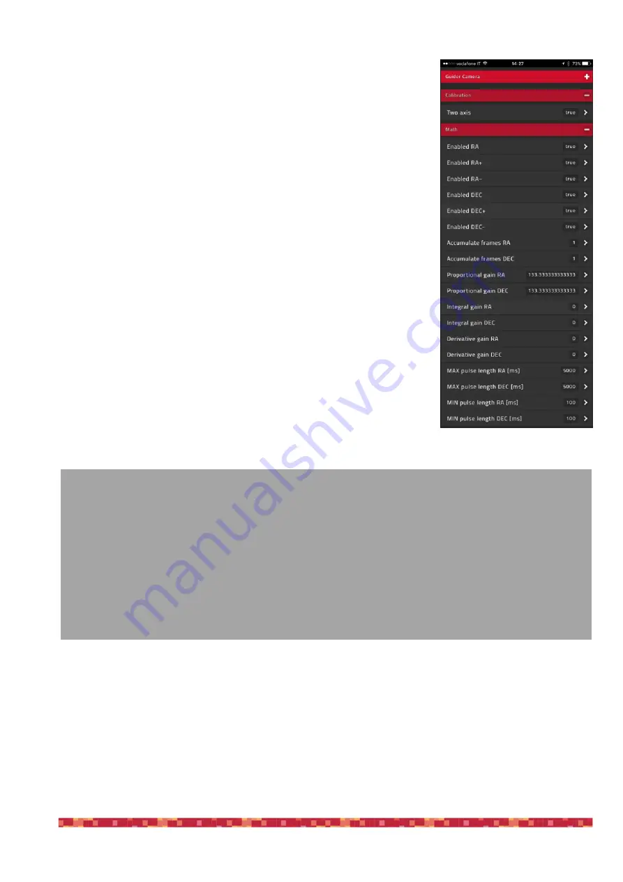
Step 6: advanced autoguide settings (optional)
If you want to adjust your guide system more accurately (for example, if you are
using high focal length telescopes, it’s advised to adjust the guide parameters
to achieve better tracking accuracy). Click the Menu button and select
Advanced Settings. In the "Calibration" submenu you find the "Two axis"
parameter. By default it is set to "true" and then EAGLE CORE will perform the
autoguide on both axes. If you use it a star tracker like the Star Adventurer that
supports autoguide corrections only on the RA axis, select "false".
The "Math" box below shows the advanced parameters associated with the
guide algorithm that uses a PID control.
All parameters can be defined separately for each axis (AR and DEC) and they
are:
1. Enable RA/RA+/RA-/DEC/DEC+/DEC- - enable or disable axis corrections
(enabled by default)
2. Accumulate frames RA e DEC - enables the average coordinate values by
using N images, and corrects at the end of the medium value (set to 1 by
default)
3. Proportional gain - the coefficient of the proportional term in the PID control.
4. Integral gain - the coefficient of the integrative term in the PID control (set to
0 by default)
5. Derivative gain - the coefficient of the derivative term in the PID control (set
to 0 by default)
6. Maximum pulse - the maximum duration of the correction pulse (set to
5000ms by default).
7. Minimum pulse - the minimum duration of the correction pulse (set to 100ms
by default).
PID control coefficients adjustments should be made empirically, using the mounted telescope and observing how
the guide quality changes according to the parameter set. The idea is to find coefficients that do not lead to too
weak or too strong guidance. We recommend adjusting first of all the proportional value and, for example, changing
by 10, anche check for the guide quality. If you notice a constant error in one direction, you can change the
integrative value that takes into account the previous guide corrections. Defining the coefficients, consider that the
values can be different for the 2 axes. If you performed a good polar alignment, DEC axis guide can be performed
at a lower frequency, on average every 2 to 4 images. This prevents excessive movement along this axis and then
removes unwanted movements.
'Maximum pulse' value is the duration of the maximum correction pulse and, in practice, it corresponds to the time
between two captures of the guide camera. It is usually not necessary to change this value. The 'Minimum pulse' is
more important as it defines the minimum duration of the correction. If the corrected correction is greater than or
page 33
What does PID mean?
Whenever a device must maintain a constant value (in our case, the position of the guide star), it needs an
algorithm that corrects the errors from the ideal position. PID means
P
roportional -
I
ntegrative -
D
erivative. First
of all, it regulates the autoguide based on the
proportional
parameter, that is, with a correction proportional to the
detected error (the greater the error, the greater the applied correction). However, if the correction is exceeded,
the autoguide can become unstable as the telescope "swings" around the ideal position of the star. This is why
the
integrative
value is added as the sum of all the errors in time and that, "remembering" the previous errors,
minimize the pendulum that can be created with the proportional system (making the entire system less reactive
and fast). To improve performance, we add the
derivative
parameter to calculate a forecast error: if the error is
increasing, this parameter will give more force to the correction than the only proportional parameter. Reversely it
will lead to a lower correction if the error is decreasing, sign that we are close to the ideal position of the guide
star.


