


45
Load Break Switch Control
ERT-200S
+
-
+
-
+
-
I
A
I
B
I
C
OR
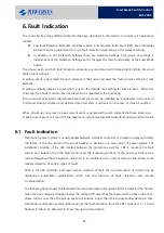
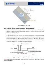
PickUp Level
Setting
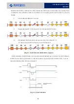
FI PickUp
[Fig. 6-3] FI Pickup Scheme
Fault detection of the state change is saved in the event buffer. And fault current is also attached to
the each time tag is saved in the buffer. Fault waveforms data can be stored up to eight and per phase
current, voltage samples which stored 10 cycles, 32 samples/cycle.
+
-
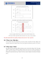
V Low Level
V
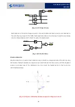
FI PickUp
FI Fault
[Fig. 6-4] FI Fault Scheme
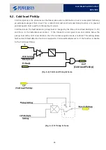
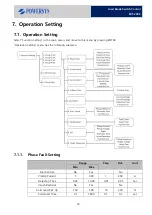
Direction Detection
Direction detection is to restrict fault indication only on faults to a designated side of the LBS. By using
this function, the fault indication can respond only to fault currents from main source, not from dispersed
sources in consumer area of the distribution line. As a result, the faulted section in the line can be
discriminated precisely.
[Fig. 6-5] Angular relationship between sequence voltage and current
Содержание ERT-200S
Страница 1: ...Feeder Remote terminal Unit ERT 200S Manual www powersys kr...
Страница 13: ...13 Load Break Switch Control ERT 200S 2 5 Function BlockDiagram...
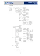
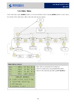
Страница 38: ...38 Load Break Switch Control ERT 200S 5 3 3 Menu structure tree Figure Menu Tree Structure...
Страница 42: ...42 Load Break Switch Control ERT 200S...
Страница 96: ...Appendix 1 Drawings 1 Enclosure Control Cabinet...
Страница 97: ...97 Load Break Switch Control ERT 200S...