29
Load Break Switch Control
ERT-200S
Number
Item
Description
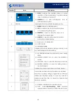
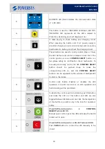
1
(1)
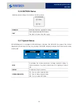
RUN:
It indicates the operation status. In normal
operation, it flicker periodically. In system problem
case, it is lighting or turned off.
(2)
ERROR:
Turn on with Self-diagnosis Error &
Communication Trouble.
2
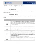
DISPLAY
Back-light LCD, 4 line with 40 characters per line.
3
(1)
MENU:
Selects the MENUrequired.
(2)
UP:
It is used to move the menu within a group
or to increase the setting point.
(3)
DOWN:
It is used to move the menu or to
decrease the changed value.
(4)
ENTER:
It is used toconfirm selection function,
and restores original display.
4
(1)
Fault A, B, C, N PHASE, SEF
(2)
SYNC. FAILED
(3)
REVERSE POWER
Indicates all the Fault detection settings currently in use
e.g. Fault Settings and Sectionalizing.
5
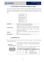
(1)
AC POWER:Indicates the external AC power supply
status.
(2)
HANDLE LOCKED: Turn on, when the HANDLE is
locked.
(3)
GAS LOW : Turn on, when the GAS status is GAS low
(4)
BATTERY LOW:Turn on, when the battery status is
low. (Discharged.)
Indicates the external Input status and check monitor.
6
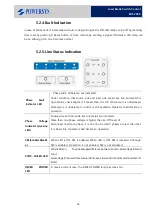
Source side and load side live line status are indicated.
More than one phase voltage is higher than an Off Level
ofDisconnect line/Open phase, it is Live line. And all 3
phases are less than that, it is Dead line. Operator shall
decide an operation.
7
(1)
ENABLE: IndicatesSection operation status.
(2)
TRIP: Indicates
Sectionalizing TRIP
sequence
operation status. The LED is lit When the LBS is open.
Содержание ERT-200S
Страница 1: ...Feeder Remote terminal Unit ERT 200S Manual www powersys kr...
Страница 13: ...13 Load Break Switch Control ERT 200S 2 5 Function BlockDiagram...
Страница 38: ...38 Load Break Switch Control ERT 200S 5 3 3 Menu structure tree Figure Menu Tree Structure...
Страница 42: ...42 Load Break Switch Control ERT 200S...
Страница 96: ...Appendix 1 Drawings 1 Enclosure Control Cabinet...
Страница 97: ...97 Load Break Switch Control ERT 200S...


