


28
Load Break Switch Control
ERT-200S
5.
Operator Control Panel
5.1.
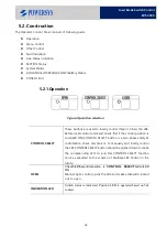
Description
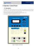
The Operator Control Panel is mounted inside the control Box on the equipment panel. The Control Panel
consists of a four-line Liquid Crystal Display (LCD) and keypad with switches and Light Emitting Diodes (LEDs)
which are used to select and monitor the functionality of the LBS.
Onthefrontpanel,thereareLED
’
sindicatingLBS
’
sstatus,functionbuttonsandLED
’
s,control
buttonsandLED
’
s,LCDbuttons,andaRS232portformaintenance.
Figure 5-1: Operator Control Panel
Содержание ERT-200S
Страница 1: ...Feeder Remote terminal Unit ERT 200S Manual www powersys kr...
Страница 13: ...13 Load Break Switch Control ERT 200S 2 5 Function BlockDiagram...
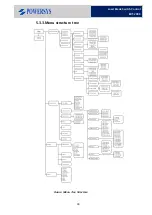
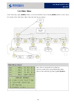
Страница 38: ...38 Load Break Switch Control ERT 200S 5 3 3 Menu structure tree Figure Menu Tree Structure...
Страница 42: ...42 Load Break Switch Control ERT 200S...
Страница 96: ...Appendix 1 Drawings 1 Enclosure Control Cabinet...
Страница 97: ...97 Load Break Switch Control ERT 200S...