


Willo Instruction Manual
5
9. Insert battery 3 into the cabinet as shown.
10. Remove the cover from battery 2 positive terminal and connect the link wire from battery
3 -ve terminal to battery 2 +ve terminal.
11. Remove the cover from battery 3 positive terminal and connect the +ve cable from the
Anderson lead (coloured red or brown) to battery 3 positive terminal.
12. Using a multimeter confirm that the voltage on the Anderson connector terminals is the
correct polarity and of the correct voltage (usually 36V nominal).
13. Push the Anderson connector through the void in shelf above Tier 2 into the top tier and
connect the Anderson connections (BATT1).
14. If a second tier of batteries is required, assemble as per above.
15. Ensure the voltage and polarity are correct as above and connect to BATT2 in the top
tier, provided the voltages are similar to BATT1.Connecting a discharged battery string
to a fully charged battery string may cause the breaker to trip. If the battery voltages are
dissimilar by more than 2V, then the discharged battery string should be charged first.
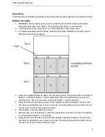
Battery Wiring Diagram.
Содержание Willo
Страница 1: ...Outdoor Integrated UPS Solution User Manual...
Страница 12: ...DOC WILLO MANUAL REV 1 4 www powerinspired com...