background image

Important

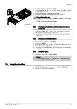
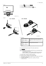
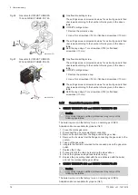
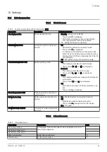
Turn the gas adjustment screw clockwise to reduce the CO

content.

Turn the gas adjustment screw counter-clockwise to increase 

the CO

2

 content.

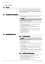
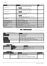
Tab.32 Checking and setting values for gas type G20 / G31

Boiler model

Maximum CO (ppm)

SIRIUS THREE FS 130

< 250

SIRIUS THREE FS 150

< 250

SIRIUS THREE FS 200

< 250

SIRIUS THREE FS 250

< 250

Tab.33 Authorised CO

2

 ranges at maximum output

Boiler model

Type G20

Type G31

SIRIUS THREE FS 130

9.2 +0.2/- 0

10 +0.2/- 0

SIRIUS THREE FS 150

9.2 +0.2/- 0

10 +0.2/- 0

SIRIUS THREE FS 200

9.2 +0.2/- 0

10.2 +0.2/- 0

SIRIUS THREE FS 250

8.85 +0.2/- 0

10.2 +0.2/- 0

8.4.3 

Setting the air/gas ratio (reduced heat input)

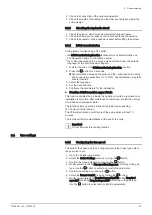
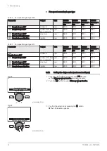
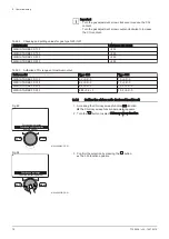
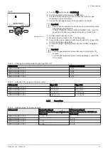
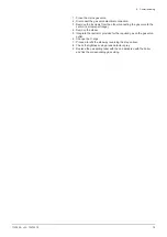
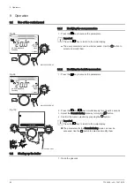
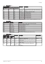
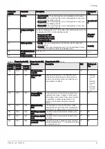
1. Accessing the Chimney sweep function 303 function.

The Chimney sweep function parameter appears.

2. Turn the 

 button to select Chimney sweep function.

3. Confirm the selection by pressing the   button. 

The 303 function appears.

Fig.93

MENU

Régime manuel

Fonction de ramonage

Fonction d’arrêt régulation

MW-4000282-FR-01

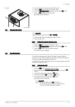
Fig.94

MENU

Fonction d’arrêt régulateur

Fonction de ramonage

MW-4000283-FR-01

8  Commissioning

76

7702639 - v03 - 10072018

Содержание SIRIUS THREE FS 130

Страница 1: ...MW 2000819 1 en Installation User and Service Manual Floor standing condensing gas boiler SIRIUS THREE FS 130 SIRIUS THREE FS 150 SIRIUS THREE FS 200 SIRIUS THREE FS 250 ...

Страница 2: ...using the product and keep it in a safe place for later reference In order to ensure continued safe and efficient operation we recommend that the product is serviced regularly Our service and customer service organisation can assist with this We hope you enjoy years of problem free operation with the product ...

Страница 3: ...Operating principle 20 4 2 1 Circulating pump 20 4 2 2 Gas air setting 20 4 2 3 Low loss header accessory 21 4 2 4 Plate heat exchanger accessories 22 4 2 5 System in cascade 23 4 2 6 Settings and safety devices 23 4 3 Main components 24 4 3 1 SIRIUS THREE FS 130 and SIRIUS THREE FS 150 24 4 3 2 SIRIUS THREE FS 200 and SIRIUS THREE FS 250 25 4 3 3 Main burner components 26 4 4 Control panel descri...

Страница 4: ...let connections 61 7 5 1 Classification 61 7 5 2 Coaxial pipes 63 7 5 3 Flue gas system accessories 63 7 5 4 Pipes in cascade not provided 63 7 5 5 Lengths of the air flue gas pipes 64 7 6 Electrical connections 67 7 6 1 Recommendations 67 7 6 2 Recommended cable cross section 67 7 6 3 Wiring the terminal blocks 67 7 6 4 Description of the power supply terminal block 68 7 6 5 Description of the se...

Страница 5: ...02 10 2 12 Locking Unlocking parameter modification 102 10 2 13 Timer program 104 10 2 14 Setting a temporary heating flow temperature 111 10 2 15 Managing boilers in cascade 111 10 3 Accessing the information menu 111 11 Maintenance 112 11 1 General 112 11 2 Standard inspection and maintenance operations 112 11 2 1 Performing the annual service 112 11 2 2 Removing the burner 112 11 2 3 Cleaning t...

Страница 6: ...17 Warranty 141 17 1 General 141 17 2 Terms of warranty 141 Contents 6 7702639 v03 10072018 ...
Страница 7: ...iance Cleaning and user maintenance shall not be made by children without supervision Caution Do not touch the flue gas pipes Depending on the boiler settings the temperature of the flue gas pipes can rise to over 60 C Caution Do not touch radiators for long periods Depending on the boiler settings the temperature of the radiators may exceed 60 C Caution Take precautions with the domestic hot wate...

Страница 8: ...iately Warning The condensation drain must not be changed or sealed If a condensate neutralisation system is used the system must be cleaned regularly in accordance with the instructions provided by the manufacturer For the end user Danger If you smell gas 1 Do not use a naked flame do not smoke do not operate electrical contacts or switches doorbell light motor lift etc 2 Shut off the gas supply ...

Страница 9: ...d off in order to guarantee the following functions Avoidance of pumps blocking Frost Protection Caution The frost protection function only protects the boiler not the heating system Caution The frost protection function does not work if the boiler is powered off Caution Remove the boiler casing only to perform maintenance and repair work Always put the casing back in place after such work Importa...

Страница 10: ... 3 Liabilities 1 3 1 Manufacturer s liability Our products are manufactured in compliance with the requirements of the various Directives applicable They are therefore delivered with the marking and any documents necessary In the interests of the quality of our products we strive constantly to improve them We therefore reserve the right to modify the specifications given in this document Our liabi...

Страница 11: ...der Give all the instruction manuals to the user 1 3 3 User s liability To guarantee optimum operation of the system you must abide by the following instructions Read and follow the instructions given in the manuals provided with the appliance Call on a qualified professional to carry out installation and initial commissioning Get your installer to explain your installation to you Have the require...

Страница 12: ...may result in minor personal injury Caution Risk of material damage Important Please note important information See Reference to other manuals or pages in this manual 2 2 Symbols used on the appliance 1 Alternating current 2 Protective earthing 3 Before installing and commissioning the appliance carefully read the instruction manuals provided 4 Dispose of used products through an appropriate recov...

Страница 13: ...ives described in these instructions must also be observed For all provisions and Directives referred to in these instructions it is agreed that all addenda or subsequent provisions will apply at the time of installation 3 1 2 Ecodesign Directive This product conforms to the requirements of European Directive 2009 125 EC on the ecodesign of energy related products 3 1 3 EC Declaration of Conformit...

Страница 14: ...heat output at 80 60 C Heating mode Maximum kW 121 5 140 3 185 9 232 8 Useful heat output at 50 30 C Heating mode Minimum kW 26 2 30 2 33 1 41 7 Useful heat output at 50 30 C Heating mode Maximum kW 130 6 150 9 200 250 Heat output Heating mode Minimum kW LHV 24 8 28 6 31 8 40 Heat output Heating mode Maximum kW LHV 123 8 143 191 240 Heat output Heating mode Minimum kW HHV 27 5 31 7 35 3 44 4 Heat ...

Страница 15: ... 5 57 5 57 5 57 5 Consumption of natural gas G20 Minimum m h 2 6 3 0 3 4 4 2 Consumption of natural gas G20 Maximum m h 13 1 15 1 20 2 25 4 Consumption of Propane G31 Minimum kg h 1 0 1 2 2 5 3 1 Consumption of Propane G31 Maximum kg h 5 1 5 9 14 8 18 6 NOx according to EN 15502 1 Class 5 mg kWh 17 23 37 39 Flue gas mass flow rate G20 Minimum kg h 43 2 50 4 54 69 Flue gas mass flow rate G20 Maximu...

Страница 16: ... 187 0 283 0 230 0 369 Part load elmin kW 0 051 0 052 0 047 0 048 Stand by PSB kW 0 004 0 004 0 004 0 004 Other specifications Standby heat loss Pstby kW 0 078 0 083 0 095 0 117 Ignition burner power consumption Pign kW Annual energy consumption QHE GJ Sound power level indoors LWA dB 63 63 Emissions of nitrogen oxides NOx mg kWh 17 23 37 39 1 Low temperature means for condensing boilers 30 C for ...

Страница 17: ... G1 1 2 5 Condensate discharge diameter 32 mm 6 Drain 1 2 3 3 2 SIRIUS THREE FS 200 and SIRIUS THREE FS 250 Fig 3 MW 5000717 3 3 5 4 7 104 300 84 1410 127 432 1104 215 5 292 5 305 5 937 5 38 38 5 98 5 25 80 98 5 51 72 1166 600 414 300 1238 1 6 2 MENU 1 Combustion air inlet 150 mm 2 Flue gas outlet 150 mm 3 Heating circuit flow R2 or DN50 PN6 flange 4 Gas inlet G1 1 2 5 Condensate discharge diamete...

Страница 18: ...1 BL BL BR BR BL BR 14 MW 5000718 3 Earth POP rivet A Power supply 230 V 50 Hz B Power supply auxiliary circuit 1 C Power supply auxiliary circuit 2 D Room thermostat E Heating circuit pump F Domestic hot water pump G Safety contact H Boiler pump I Auxiliary sensor 1 J Auxiliary sensor 2 K Outside sensor L Domestic hot water sensor M Room temperature sensor 1 N Room temperature sensor 2 O Room tem...

Страница 19: ...ensor L Domestic hot water sensor M Room temperature sensor 1 N Room temperature sensor 2 O Room temperature sensor 3 P Boiler pump modulation PWM 1 Flow temperature sensor 2 Return temperature sensor 3 Hydraulic pressure sensor 4 Flue gas sensor 5 Control panel display 6 Ionisation probe 7 Spark plug 8 Igniter 9 Gas valve 10 Safety thermostat 11 Fan 12 Safety thermostat on the combustion chamber ...

Страница 20: ...demand and the actual temperatures measured by the temperature sensors The gas and air are mixed in the Venturi The gas air ratio command function ac curately adjusts the quantities of gas and air required This provides optimum combustion over the entire output range The gas air mixture is sent to the burner located upstream of the heat exchanger SIRIUS THREE FS 200 SIRIUS THREE FS 250 An air inta...

Страница 21: ...s particularly when several circuits are operating independently from one another It provides the option of having secondary circuits at different temperatures It allows air to be evacuated thanks to its degassing function It enables decanting and removal of sludge via the sludge removal function Fig 7 Functional diagram of a boiler with a low loss header MW 1000021 06 3 7 1 5 9 8 6 2 4 10 1 Boile...

Страница 22: ...he secondary heating circuit water Fig 9 Functional diagram of a boiler with plate heat exchanger MW 5000803 01 3 7 1 5 9 8 6 2 4 10 11 12 13 1 Boiler 2 Plate heat exchanger kit 3 Plate heat exchanger 4 Air vent 5 Drain valve 6 Heating circuit flow 7 Valve 8 Safety valve 9 Modulating circulating pump 10 Non return valve 11 Drain valve 12 Valve 13 Expansion vessel Fig 8 MW 5000804 01 4 Description ...

Страница 23: ...nected NTC flue gas sensor The control panel blocks the gas supply to the burner in the event of overheating To resume normal operation of the boiler switch off the boiler and switch it back on again with the ON OFF switch Flame detector by ionisation The boiler is put into safety lock down in the event of gas shortage or incomplete cross lighting on the burner Hydraulic pressure switch Thanks to ...

Страница 24: ...ke of gas to the burner in the event of a blockage in the discharge pipe for the combustion products or the combustion air inlet pipe 4 3 Main components 4 3 1 SIRIUS THREE FS 130 and SIRIUS THREE FS 150 Fig 11 MW 5000720 2 19 20 21 18 17 14 15 8 5 6 4 13 12 10 22 23 24 25 1 7 9 11 16 3 2 26 1 Control panel 2 Flue gas connection 3 Flue gas measuring point 4 Controller PCB 5 Mounting point for a ma...

Страница 25: ...ol 8 Mounting point for communication module OCI 345 Caution Danger of short circuit on the OCI 345 communication module if it is fixed in another emplacement 9 Mounting point for conversion module AGU 2 551 10 Gas valve 11 Ionisation probe 12 Burner 13 Ignition electrode 14 Flame inspection window 15 Safety thermostat on the combustion chamber door 16 Ignition transformer 17 Hydraulic pressure se...

Страница 26: ... Control panel description 4 4 1 Description of the keys Shortcuts menu key Quick access to the operating modes MENU Menu key Selection and confirmation button Rotary button for navigating between menu or parameter screens Push button to select a menu parameter or to confirm a value action Fig 13 Burner for SIRIUS THREE FS 130 and SIRIUS THREE FS 150 MW 4000265 1 3 2 1 8 9 6 7 5 4 10 Fig 14 Burner...

Страница 27: ...active 1 2 3 2 Zone 2 active 1 2 3 3 Zone 3 active Symbol displayed No symbol heating circuit not connected Fixed symbol heating circuit connected Flashing symbol heating requested Operating mode Domestic hot water activated Important The heating 1 2 3 is off during production of domestic hot water Operating mode Comfort Eco override mode Operating mode Automatic according to the timer programs Sw...

Страница 28: ... a package that includes A floor standing gas boiler An installation user and maintenance manual A data plate 4 6 Accessories options A detailed list of accessories and options can be found in our catalogue 4 Description of the product 28 7702639 v03 10072018 ...

Страница 29: ...or the heating circuits Use these products carefully following their manufacturers instructions For an existing system Before carrying out installation of the boiler drain and flush the system to eliminate sludge and pollutants using the appropriate products permitted see products recommended above Any foreign particles in the heating circuit impair proper functioning of the boiler e g overheating...

Страница 30: ...600 litres hour where T 20 C 5 Operating water flow rate at nominal heat output 7500 litres hour where T 15 C ΔT Temperature difference between the flow water and the return water in the boiler 1 Q flow rate litres hour 2 H pressure in millibar mbar 3 Operating water flow rate at nominal heat output 4310 litres hour where T 30 C 4 Operating water flow rate at nominal heat output 6460 litres hour w...

Страница 31: ...ution Install the thermodynamic water heater in a frost free environment Caution Install the boiler on a solid stable structure able to bear its weight Caution Do not stock chloride or fluoride compounds close to the boiler They are particularly corrosive and may contaminate the combustion air Chloride and fluoride compounds are present in aerosol sprays paints solvents cleaning products washing p...

Страница 32: ...10 If the boiler is installed in closed premises respect the minimum dimensions given in the diagram below Also allow for openings to obviate the following hazards Accumulation of gas Overheating of the premises Great Britain Minimum cross section of openings see BS 5440 Part 1 and Part 2 and BS 6644 Ventilation to be provided for the boilers 5 3 2 Overall space needed for the boiler To ensure ade...

Страница 33: ... to be provided for boilers equipped with a low loss header kit plate heat exchanger kit or cascade kit Tab 14 Boiler model A B C D E SIRIUS THREE FS 130 1100 500 400 500 1000 SIRIUS THREE FS 150 1100 500 400 500 1000 SIRIUS THREE FS 200 1100 500 750 500 1000 SIRIUS THREE FS 250 1100 500 750 500 1000 Fig 22 MW 4000216 02 E C A D B Fig 23 MW 4000217 02 C A B E D 5 Before installation 7702639 v03 10...

Страница 34: ...açade of the area to be heated on the north if possible Half way up the wall of the area to be heated Under the influence of changes in the weather Protected from direct sunlight Easy to access Fig 25 MW 8800N001 3 2 1 2 1 1 2 H 1 2 H min 2 5 m 1 2 H min 2 5 m 1 2 Z H Z 1 Optimum location 2 Possible position H Inhabited height controlled by the sensor Z Inhabited area controlled by the sensor Posi...

Страница 35: ...ent Handle the appliance with gloves Transport the pallet carrying the appliance using a pallet truck a forklift truck or a 4 wheel removals cart Do not use the top cover of the appliance for transport lifting Transport the appliance vertically Unpacking initial preparation 1 Remove the cardboard packaging and polystyrene packing Fig 27 20 MW 2000774 1 Fig 28 MW 2000775 2 1 5 Before installation 7...

Страница 36: ...n the slots provided 3 Lift and tilt the control panel 4 Disconnect the earth wire 5 Pull and lift the top panel Fig 29 MW 2000776 2 2 Fig 30 3 MW 2000777 1 Fig 31 MW 2000778 1 4 Fig 32 MW 2000779 1 5 5 Before installation 36 7702639 v03 10072018 ...

Страница 37: ...oiler Sling attachment angle β 60 SIRIUS THREE FS 130 126 kg SIRIUS THREE FS 150 132 kg Caution Moving the boiler is a job for two people Follow the usual handling techniques and use adequate safety equipment 9 Close the boiler 1 Adjustment range for the feet 30 mm 10 Level the boiler using the adjustable feet Fig 33 6 MW 2000780 1 7 7 Fig 34 100 kg MW 2000781 1 8 8 8 Fig 35 10 MW 2000782 2 1 5 Be...

Страница 38: ...rt the pallet carrying the appliance using a pallet truck a forklift truck or a 4 wheel removals cart Do not use the top cover of the appliance for transport lifting Transport the appliance vertically Unpacking initial preparation with rails 1 Remove the cardboard and the polystyrene packing 2 Remove the protective plastic Fig 36 20 MW 2000773 1 Fig 37 MW 2000765 2 1 2 5 Before installation 38 770...

Страница 39: ...ing firmly on the slots provided 4 Remove the 2 unloading rails by unscrewing the 4 screws 5 Rotate the 2 rails by 180 Fig 38 MW 2000766 2 3 Fig 39 MW 2000767 2 4 Fig 40 MW 2000768 1 5 180 5 Before installation 7702639 v03 10072018 39 ...

Страница 40: ... the pallet Caution Ensure there is sufficient space to move the boiler 7 Remove the four screws attaching the boiler to the pallet Fig 41 MW 2000769 2 6 6 4x i Fig 42 MW 2000770 2 7 7 7 7 5 Before installation 40 7702639 v03 10072018 ...

Страница 41: ...ng the boiler is a job for two people Follow the usual handling techniques and use adequate safety equipment 9 Close the boiler 1 Adjustment range for the feet 20 mm 10 Level the boiler using the adjustable feet Fig 43 MW 2000771 2 200 kg 8 Fig 44 MW 2000772 2 10 1 5 Before installation 7702639 v03 10072018 41 ...

Страница 42: ...s 1 Remove the cardboard and the polystyrene packing 2 Remove the protective plastic 3 Remove the front panel by pulling firmly on the slots provided Fig 45 MW 2000765 2 1 2 Fig 46 MW 2000766 2 3 5 Before installation 42 7702639 v03 10072018 ...

Страница 43: ... Lift and tilt the control panel 5 Disconnect the earth wire 6 Pull and lift the top panel Fig 47 MW 4000295 1 4 Fig 48 MW 4000296 1 5 Fig 49 6 MW 4000297 1 5 Before installation 7702639 v03 10072018 43 ...

Страница 44: ...allet 9 Use slings not provided to move the boiler Sling attachment angle β 60 SIRIUS THREE FS 200 212 kg SIRIUS THREE FS 250 232 kg Caution Moving the boiler is a job for two people Follow the usual handling techniques and use adequate safety equipment 10 Close the boiler Fig 50 8 8 8 8 MW 4000298 1 7 Fig 51 MW 4000299 1 200 kg 9 5 Before installation 44 7702639 v03 10072018 ...

Страница 45: ...11 Level the boiler using the adjustable feet 1 Adjustment range for the feet 20 mm Fig 52 MW 4000300 2 11 1 5 Before installation 7702639 v03 10072018 45 ...

Страница 46: ...ion valve 16 Closed expansion vessel 18 Heating circuit fill point France with disconnector according to prevailing regulations 24 Domestic hot water tank exchanger primary inlet 25 Domestic hot water tank exchanger primary outlet 26 DHW booster pump 27 Non return valve 30 Calibrated and sealed safety unit France 7 bar 0 7 MPa with opening on the discharge pipe 30e Drain valve 31 Independent domes...

Страница 47: ...MW 3000114 06 167 21 33 38 34 26 11 1 2 3 X40 11 Heating pump 21 Outside temperature sensor 26 DHW booster pump 33 Domestic hot water temperature sensor 34 Primary pump 38 Remote control 167 Boiler control panel Important Relay the pumps if the current exceeds 1 A max per output 6 Connecting diagrams and configuration 7702639 v03 10072018 47 ...

Страница 48: ...lve 30 Calibrated and sealed safety unit France 7 bar 0 7 MPa with opening on the discharge pipe 30e Drain valve 31 Independent domestic hot water tank 33 Domestic hot water temperature sensor 34 Modulating boiler pump 35 Low loss header optional 38 Remote control with or without room temperature sensor 44 France 65 C safety thermostat with manual reset for underfloor heating DTU 65 8 NF P52 303 1...

Страница 49: ...ith manual reset for underfloor heating France DTU 65 8 NF P52 303 1 117 Three way mixing valve 158 Flow temperature sensor 167 Boiler control panel Important Relay the pumps if the current exceeds 1 A max per output 6 2 3 Configuration 1 Go to the installer parameters 2 Set the following parameters on the boiler Tab 15 Boiler settings 1 underfloor heating circuit 1 direct circuit 1 domestic hot w...

Страница 50: ...safety unit France 7 bar 0 7 MPa with opening on the discharge pipe 30e Drain valve 31 Independent domestic hot water tank 33 Domestic hot water temperature sensor 34 Modulating boiler pump 35 Low loss header 38 Remote control with or without room temperature sensor 44 France 65 C safety thermostat with manual reset for underfloor heating DTU 65 8 NF P52 303 1 Austria safety device to safeguard ag...

Страница 51: ...sensor 26 DHW booster pump 33 Domestic hot water temperature sensor 34 Primary pump 38 Room temperature sensor 44 France 65 C safety thermostat with manual reset for underfloor heating DTU 65 8 NF P52 303 1 Austria safety device to safeguard against overheating according to the type of underfloor heating Other countries safety device to safeguard against overheating of the underfloor heating in ac...

Страница 52: ...Configuration for a master boiler and slave boilers 1 Access the installer parameters of the master boiler 2 Set the following parameters on the master boiler Tab 18 Configuration of the master boiler in a cascade Parameter num ber Parameter Adjustment required Description 5977 Function input H5 None Deactivation of the thermostat on terminal block M1 1 2 6030 Relay output QX21 module 1 three way ...

Страница 53: ... setting Setting the slave boiler clock with a master boiler 6 4 Controlling a boiler in 0 10 V mode 6 4 1 Electrical connection Fig 59 Boiler in 0 10 V mode 1 2 3 4 Aux 1 2 230 V TA TS L N T1 T2 L L N N S1 S2 L N MW 3000041 05 34 AVS75 38 X40 X41 34 Primary pump 38 Remote control with or without room temperature sensor Important Relay the pumps if the current exceeds 1 A max per output 6 4 2 Conf...

Страница 54: ...tional 6046 Function input H2 module 1 Consumer request VK1 10V 6049 Voltage value 1 H2 module 1 0 5 1 6050 Funct value 1 H2 module 1 250 1 6051 Voltage value 2 H2 module 1 10 1 6052 Funct value 2 H2 module 1 800 1 2 1 Default setting 2 This parameter setting is an example The value 800 means that at 10 V the set point will be 80 C 6 Connecting diagrams and configuration 54 7702639 v03 10072018 ...

Страница 55: ...s codes of practice and the recommendations in this manual 7 2 Accessing the internal boiler components 1 Remove the front panel by pulling firmly on the notches provided 2 Lift and tilt the panel holding the control panel Fig 60 MW 4000259 2 1 Fig 61 MW 4000260 1 2 7 Installation 7702639 v03 10072018 55 ...

Страница 56: ...arth wire 4 Pull and lift the top panel 5 Unhook the panel holding the control panel then place it on the boiler Fig 62 MW 4000261 1 3 Fig 63 MW 4000262 1 4 Fig 64 MW 4000263 1 5 5 7 Installation 56 7702639 v03 10072018 ...

Страница 57: ...valve and the expansion vessel between the stop valves and the boiler Always install a safety valve calibrated to 6 bar on the heating circuit The safety valve can be connected to a venting pot The safety valve must not be used to drain the heating circuit See In the case of an assembly with a low loss header use the assembly instructions for the low loss header If using a cascade kit use the asse...

Страница 58: ... the boiler s inlet and outlet valves not provided Important To facilitate maintenance work we recommend mounting a stop valve on the heating flow and return pipes Caution Position the safety valve between the boiler and the stop valve 5 Fit the circulating pump on the heating return pipe circulating pump not provided Fig 66 1 MW 4000266 1 2 Fig 67 4 3 MW 4000267 1 Fig 68 5 MW 4000268 1 7 Installa...

Страница 59: ...he boiler s heating flow output 3 Screw the heating circuit return bracket onto the boiler s heating return output 4 Mount the filling and drain valves to the boiler s inlet and outlet valves not provided Important To facilitate maintenance work we recommend mounting a stop valve on the heating flow and return pipes Caution Position the safety valve between the boiler and the stop valve Fig 69 MW ...

Страница 60: ...ns on filling the heating circuits with water BS 7074 BS 6644 BS EN 12828 Caution Only qualified professionals are authorised to carry out maintenance work on the boiler and the heating system 7 3 3 Connecting the condensate discharge pipe The condensate discharge pipe is located inside the boiler Do not block the condensate discharge pipe Set the discharge pipe at a gradient of at least 30 mm per...

Страница 61: ...ing Close the main gas valve before starting work on the gas pipes The gas pipes are not provided Danger The diameters of the pipes must be defined in accordance with the standards in force in your country 1 Remove the anti dust plug located on the boiler s gas inlet 2 Fit a gas stop valve not provided on the boiler s gas inlet G1 1 2 3 Connect the gas inlet pipe to the gas stop valve Caution Ensu...

Страница 62: ...e and combustion product discharge pipes must not be plan ned on opposite walls of the building C63 The maximum pressure drop in the pipes ΔP must not exceed the values given in the table below The pipes must be certified for this type of use and for a temperature of more than 100 C The terminal part of the flue gas pipe must be certified as complying with the EN 1856 1 Standard If installing disc...

Страница 63: ...or the 45 elbow If discharging to the outside the discharge intake pipe must stick out of the wall by at least 18 mm to allow fitting of the aluminium rosette and its sealing unit and thus prevent any infiltration of water Insertion of a 90 elbow reduces the total length of the pipe by 1 metres Insertion of a 45 elbow reduces the total length of the pipe by 0 5 metres The first 90 elbow is not tak...

Страница 64: ...table s Caution Be careful that the discharge pipe outlet for combustible products is not directed towards a habitation zone B23p configuration All countries except Italy Ventilation of the premises in accordance with the NFP 45 204 or DTU 61 1 standard Italy Ventilation of the premises in accordance with the UNI CIG 7129 2001 standard All countries Lengths L1 L2 and L3 are obtained with Centrotec...

Страница 65: ...7 39 23 L3 2m 2 elbows L1 L2 flexible m 7 9 19 13 L3 5m 2 elbows L1 L2 rigid m 17 23 36 19 L3 5m 2 elbows L1 L2 flexible m 6 15 10 Configuration C13 Important Pipes subject to technical evaluation 14 08 1289 Fig 80 MW 4000280 1 1 3 4 L L L L 2 130 150 kW 200 250 kW 1 3 4 L L L L 2 Tab 25 Maximum length for configuration C13 Configuration Unit SIRIUS THREE FS 130 SIRIUS THREE FS 150 SIRIUS THREE FS...

Страница 66: ... 110 Ø 110 Ø 160 Ø 160 5 m L 8 L 8 L 20 L 11 6 m L 8 L 8 L 22 L 12 7 m L 6 L 6 L 16 L 6 8 m L 7 L 7 L 20 L 9 Configuration C53 Important Pipes subject to technical evaluation 14 08 1289 Tab 27 Maximum length for configuration C53 Configuration Unit SIRIUS THREE FS 130 SIRIUS THREE FS 150 SIRIUS THREE FS 200 SIRIUS THREE FS 250 mm Ø 110 Ø 110 Ø 160 Ø 160 9 m L1 L2 max 20 L1 max 10 L1 L2 max 20 L1 m...

Страница 67: ...ep the various electrical cables far enough from the heating pipes so that they cannot be damaged by the effect of the heat 7 6 2 Recommended cable cross section Decide on the cable according to the following information Distance of the appliance from the power source Upstream protection Neutral operating conditions Tab 28 Specifications of the power cable and the power source Cable cross section ...

Страница 68: ...heck that the wire is attached by pulling it gently upwards If it comes out of the housing repeat step 3 7 6 4 Description of the power supply terminal block Fig 86 MW 1000015 06 1 2 3 4 Aux 1 2 230 V TA TS L N T1 T2 L L N N S1 S2 L N 2 4 6 8 5 7 1 3 1 Power supply 230 V 50 Hz 2 Power supply auxiliary circuit 1 Fig 84 MW 3000038 05 2 Fig 85 MW 3000039 04 3 7 Installation 68 7702639 v03 10072018 ...

Страница 69: ... any circumstances The sum of the currents from all outlets must not exceed 6 3 A 7 6 5 Description of the sensor terminal block Fig 87 MW 1000016 05 1 1 2 1 2 3 1 2 1 2 3 2 3 1 2 3 4 5 6 8 7 1 Auxiliary sensor 1 BX3 flow sensor cascade return connection 2 Auxiliary sensor 2 BX2 heating circuits collector flow sensor connection 3 Outside sensor 4 Domestic hot water sensor BX1 5 Room temperature se...

Страница 70: ... SIRIUS THREE FS 130 and SIRIUS THREE FS 150 Before filling the heating installation rinse it thoroughly 1 Open the plug on the automatic air vent 2 Fill the heating system until you reach a pressure of between 0 15 and 0 2 MPa 1 5 and 2 bar 3 Check the tightness of the hydraulic connections 4 Completely vent the heating circuit for optimum running For more information see Flushing new installatio...

Страница 71: ...r hemp flux 2 Thoroughly flush the installation until the water runs clear and shows no impurities 7 7 4 Flushing an existing installation 1 Remove any sludge from the installation 2 Flush the installation 3 Clean the installation with a universal cleaner to eliminate debris from the system copper hemp flux 4 Thoroughly flush the installation until the water runs clear and shows no impurities 7 7 ...

Страница 72: ...tion in the room in which the system is installed 9 Check the flue gas connections 10 Test the boiler at full load 11 Test the boiler at part load 8 3 Commissioning procedure 8 3 1 Checking the gas inlet Danger Ensure that the boiler is switched off 1 Open the main gas valve 2 Open the gas valve on the boiler 3 Open the front panel 4 Check the gas supply pressure at the pressure outlet on the gas ...

Страница 73: ... 312 Deaeration apprx 10min This function enables the air inside the heating circuit to be removed once installation is complete after maintenance operations or after the primary circuit has been drained of water The function starts up automatically during initial commissioning 311 Commissioning function The PCB will activate an on off cycle of the pump which will last 10 minutes The function will...

Страница 74: ...THREE FS 250 9524 Required speed LF minimum rpm 1950 2000 1370 1510 9524 Required speed LF minimum for boil ers in cascade rpm 1950 2000 1370 1510 9529 Required speed HF 2441 Fan speed heating max maximum rpm 5800 6900 5200 5830 9512 Required speed ignition ignition rpm 2500 2500 2200 2200 8 4 2 Setting the air gas ratio maximum heat input 1 Accessing the Chimney sweep function 303 function The Ch...

Страница 75: ...und the sensor is completely sealed when taking measurements SIRIUS THREE FS 130 and SIRIUS THREE FS 150 Insert the sensor into the flue gas measurement point to at least 8 cm 9 Set the boiler s heat input to 100 at full load 10 Measure the percentage of CO2 in the flue gases 11 Compare the values measured with the set point values in the Control and setting values table 12 If necessary adjust the...

Страница 76: ... 130 9 2 0 2 0 10 0 2 0 SIRIUS THREE FS 150 9 2 0 2 0 10 0 2 0 SIRIUS THREE FS 200 9 2 0 2 0 10 2 0 2 0 SIRIUS THREE FS 250 8 85 0 2 0 10 2 0 2 0 8 4 3 Setting the air gas ratio reduced heat input 1 Accessing the Chimney sweep function 303 function The Chimney sweep function parameter appears 2 Turn the button to select Chimney sweep function 3 Confirm the selection by pressing the button The 303 ...

Страница 77: ...ase the CO2 content Turn the gas adjustment screw counter clockwise to reduce the CO2 content Tab 34 Checking and setting values for gas type G20 G31 Boiler model Maximum CO ppm SIRIUS THREE FS 130 250 SIRIUS THREE FS 150 250 SIRIUS THREE FS 200 250 SIRIUS THREE FS 250 250 Tab 35 Authorised CO2 ranges at minimum output Boiler model Type G20 Type G31 SIRIUS THREE FS 130 8 5 0 0 2 9 7 0 0 2 SIRIUS T...

Страница 78: ...130 and SIRIUS THREE FS 150 Caution Only a fully trained qualified professional may carry out the following operations The boiler is pre set in the factory to run on natural gas H G20 Adaptation kits are available for propane G31 1 Close the mains gas valve 2 Disconnect the gas valve electrical connection 3 Remove the two nuts from the flange under the gas valve 4 Remove the 4 screws from the flan...

Страница 79: ... Remove the elbow 5 Integrate the restrictor provided for the required gas on the gas valve outlet 6 Change the O rings 7 Proceed to refit the elbow by reversing the steps above 8 Check the tightness using a leak detector spray 9 Replace the gas setting label with the one delivered with the boiler and tick the corresponding gas setting 8 Commissioning 7702639 v03 10072018 79 ...

Страница 80: ... at least 6 seconds 3 Select the Commissioning menu by turning the button 4 Confirm the menu selection by pressing the button Important Press the MENU key to return to the main display The parameters for the Commissioning mode can now be accessed Use the button to select and modify them 9 2 Starting up the boiler 1 Open the gas cock Fig 98 MW 3000052 EN 02 MENU 14 13 1 5 bar 18 February 2014 Tuesd...

Страница 81: ...tion The electronic management system of the boiler includes protection against frost If the water temperature falls below 5 C the burner starts up in order to provide a water temperature of 30 C This function only works if the boiler is turned on the gas supply open and the hydraulic pressure correct 9 4 1 Activating the Off 1 Press the key to access the shortcuts menu 2 Select the parameter Cent...

Страница 82: ...10min On activates the function Off exits the function To activate a special function 1 From the main menu simultaneously press the MENU keys for approximately 6 seconds The name of the functions 301 303 304 312 flashes 2 Turn the button to select the required function 3 Press the button to activate the selected function 4 Confirm the selection by pressing the button The menu for the selected func...

Страница 83: ...ed in Comfort mode The symbols 1 2 3 and are displayed Reduced The heating is activated in Eco mode The symbols 1 2 3 and are displayed Timed The heating operates according to the defined tim er programs The symbols and 1 2 3 are displayed Off The boiler is shut down and frost protection is ac tive The symbol is displayed Room temperature CH1 Room temperature set point in comfort mode Hot water he...

Страница 84: ...mber of the After Sales Service 0845 070 1057 10 1 3 List of user parameters Tab 40 Structure of the user menu Menu Feature Set time and date Setting the time and date Operator section Change Language Programming lock Time program Time hot water Predefined or custom programs with a maximum of 3 comfort or domestic hot water production ranges for each 24 hours Holiday Settings Eco heating or frost ...

Страница 85: ...ecting the days or group of days for the timer program 574 Mon Sun Selecting a default timer program 561 1st Time ON Start of timer period 1 562 1st Time OFF End of timer period 1 563 2nd Time ON Start of timer period 2 564 2nd Time OFF End of timer period 2 565 3rd Time ON Start of timer period 3 566 3rd Time OFF End of timer period 3 576 Default values Reset the timer programming parameters Yes ...

Страница 86: ...is dependent on the timer pro gram Reduced the room temperature set point is the reduced set point Parameters 712 1010 1310 On the room temperature set point is the comfort set point Parameters 710 1010 1310 On 710 1010 1310 Comfort setpoint 20 C 712 1012 1310 Reduced temp setpoint 16 C 10 1 4 List of installer parameters Tab 47 Structure of the installer menu Menu Sub menu Installer Operator sect...

Страница 87: ...meter number Parameter Description Unit Factory set ting Heating circuit 1 Heating circuit 2 Heating circuit 3 714 1014 1314 Frost protection setpoint C 6 720 1020 1320 Heating curve slope Heating curve gradient The regulator calcu lates the flow temperature set point which is used for the control system according to out side weather conditions Heating circuit 1 1 5 Heating circuit 2 1 5 Heating c...

Страница 88: ... function is inoperative Curing functional heating Active for 7 days 3 days at 25 C and 4 days at 55 C Curing heating Active for 18 days 6 days from 25 C to 55 C increasing by 5 C a day 6 days at 55 C 6 days from 55 C to 25 C diminishing by 5 C a day Functional curing heating Functional Heat ing cycle first and then Ready for Occupa tion Manually Regulation is based on the Man ual Control Drying s...

Страница 89: ...a function is running 45 C 1680 Optg mode changeover In cases of external switching via the Hx inputs the regime to which the switch must be made must first be defined None Off None Tab 51 Boiler Settings menu Parameter number Parameter Description Unit Factory set ting 2214 Setpoint manual control In manual mode the flow temperature set point can be set to a fixed value C 80 C 2441 Fan output hea...

Страница 90: ...election of the domestic hot water sensor Hot water sensor B3 Domestic hot water sensor for tank Thermostat The sensor used for domestic hot water is a thermostat Hot water sensor B3 5731 HW controlling element Type of actuator for controlling the domestic hot water requirement No charging request No function Charging pump Domestic hot water loading is done with a pump Diverting valve Domestic hot...

Страница 91: ...e relay is controlled according to the settings on timer program 5 Buffer return valve Y15 Solar pump ext exch K9 Solar ctrl elem buffer K8 Solar ctrl elem swi pool K18 Contact for heating the swimming pool with solar energy if using several heat exchangers Cons circuit pump VK2 Q18 Cascade pump Q25 Boiler pump common to all boilers in a cas cade St tank transfer pump Q11 Hot water mixing pump Q35...

Страница 92: ...return sensor B70 Cascade return sensor Swimming pool sensor B13 Swimming pool sensor Solar flow sensor B63 Solar flow sensor for measuring efficiency Solar return sensor B64 Solar return sensor for measuring efficien cy Primary exch sensor B26 None 5932 Sensor input BX3 See Sensor input BX2 None 5970 Function input H4 None Default setting for boilers with domestic hot water tank Flow measurement ...

Страница 93: ...nal resource Operating level HW The temperature level can be adjusted by a contact external timer program rather than by the internal timer pro gram Operating level CH1 The temperature level can be adjusted by a contact external timer program rather than by the internal timer pro gram Operating level CH2 The temperature level can be adjusted by a contact external timer program rather than by the i...

Страница 94: ...ler Not used Solar HW Settings corresponding to the operator chapter on Thermal So lar Primary contr system pump Not used Without 6024 6026 6028 Funct input EX21 module 1 Funct value 2 H2 module 3 Funct value 2 H2 module 3 None Limit thermostat CH None 6030 6033 6036 Funct value 2 H2 module 3 Funct value 2 H2 module 3 Funct value 2 H2 module 3 See QX1 relay outlet without 6031 6034 6037 Funct valu...

Страница 95: ... 6705 SW diagnostic code Software troubleshooting code currently pending 6706 Burn ctrl phase lockout pos Locking phase indicating the place where the error occurred 6710 Reset alarm relay Alarm relay reset 6800 History 1 Last error that occurred 6805 SW diagnostic code 1 Last troubleshooting code that occurred 6806 Burner control phase 1 Last locking phase indicating the place where the error occ...

Страница 96: ...u Parameter num ber Parameter Description 8000 State central heating CH1 8001 State central heating CH2 8002 State central heating CH3 8003 State hot water 8005 State boiler 8007 State solar 8008 State solid fuel boiler 8009 State burner 8010 State buffer 8011 State swimming pool Tab 58 Diagnostics heat generation menus Parameter num ber Parameter Description 8310 Boiler temperature Control temp V...

Страница 97: ...ting interface 6624 Manual source lock 10 2 Setting the parameters 10 2 1 Setting the date and time 1 Press the MENU key to access the parameters 2 Select the Set time and date menu by turning the button 3 Confirm the menu selection by pressing the button The parameter Hours minutes appears 4 Confirm the parameter selection by pressing the button The parameter flashes it can be modified 5 Modify t...

Страница 98: ...e parameter Central heating mode CH1 by turning the button 3 Press the button to confirm 4 Select the appropriate operating mode 5 Press the button to confirm Important Press the MENU key to return to the main display 10 2 4 Forcing domestic hot water production 1 Press the key to access the shortcuts menu 2 Select the parameter 316 Hot water boost by turning the button 3 Press the button to start...

Страница 99: ...eating by turning the button 3 Press the button to confirm 4 Select the appropriate operating mode 5 Press the button to confirm Important Press the MENU key to return to the main display 10 2 7 Setting the domestic hot water temperature set point 1 Press the key to access the shortcuts menu 2 Select the parameter Hot water temp setpoint by turning the button 3 Press the button to confirm 4 Turn t...

Страница 100: ...longed absences The various parameters are used to program one of eight Holiday periods Important When the function is activated the symbol is displayed 1 Press the MENU key to access the parameters 2 Select the Holiday heating CH1 menu by turning the button 3 Confirm the menu selection by pressing the button The Select parameter appears 4 Select the Holiday period to be programmed by turning the ...

Страница 101: ... selection by pressing the button 10 2 10 Using the boiler according to thermal output Using the boiler according to thermal output makes it possible to calibrate the gas valve 1 From the home screen press the and MENU keys simultaneously 2 Select the parameter Controller stop function by turning the button 3 Press the button to confirm The parameter Controller stop function On appears Fig 112 MW ...

Страница 102: ... button to temporarily modify the temperature set point on the selected heating circuit 4 Press the button to confirm The selected heating circuit is active 10 2 12 Locking Unlocking parameter modification It is possible to lock all functions associated with the MENU key to prevent unauthorised persons from modifying the parameters Locking parameter modification 1 Press the MENU key to access the ...

Страница 103: ...ress the MENU key to access the user parameters menu 2 Press the key and the button simultaneously for around 6 seconds Important Unlocking is temporary and lasts 1 minute temporarily unlocked is displayed 3 Press the MENU key to access the user parameters menu 4 Select the Operator unit menu by turning the button 5 Confirm the menu selection by pressing the button 6 Select menu 27 Programming loc...

Страница 104: ...nd 3 and the parameters Select days 560 for domestic hot water Pre setting selected Days programmed Mon Sun Monday Tuesday Wednesday Thursday Friday Satur day Sunday Mon Fri Monday Tuesday Wednesday Thursday Friday Sat Sun Saturday Sunday Mon Monday Tue Tuesday Wed Wednesday Thu Thursday Fri Friday Sat Saturday Sun Sunday 1 Period of operation at the comfort temperature 2 Period of operation in re...

Страница 105: ...561 562 563 564 565 566 domestic hot water Single days Pre set programs On 1 Off 1 On 2 Off 2 On 3 Off 3 Monday Tuesday Wed nesday Thursday Friday Saturday Sunday 06 00 08 00 11 00 13 00 17 00 23 00 Selecting a Timer Program 1 Select a heating circuit 2 Press the MENU key to access the parameters 3 Select the Time central heating CH1 menu by turning the button Important For heating circuits 2 and ...

Страница 106: ...d time range by turning the button 11 Confirm the time range selection by pressing the button Important Press the MENU key to return to the main screen For more information see Copying a time range page 108 Customising the time ranges 1 Select a heating circuit 2 Press the MENU key to access the parameters Fig 123 MW 3000130 EN 02 MENU Mon Sun Time central heating CH1 Select days Fig 124 MW 300013...

Страница 107: ... button 8 Select the parameter 1st Time ON 501 521 541 or 561 by turning the button 9 Confirm the menu selection by pressing the button The beginning of the first time range flashes 10 Select the end of the first time range by turning the button Important Select the value in order not to program a first time range 11 Confirm the value programmed by pressing the button Fig 126 MW 3000071 EN 03 MENU...

Страница 108: ...3 523 543 or 563 3rd Time ON 505 525 545 or 565 End of the time range 1st Time OFF 502 522 542 or 562 2nd Time OFF 504 524 544 or 564 3rd Time OFF 506 526 546 or 566 Important Press the MENU key to return to the main screen For more information see Copying a time range page 108 Copying a time range Important It is possible to copy a time range from one day to another It is not possible to copy a t...

Страница 109: ...py 515 535 555 or 575 by turning the button 10 Confirm the menu selection by pressing the button The parameter Copy to appears 11 Select a target day by turning the button 12 Confirm the menu selection by pressing the button Important Repeat the copy to other days if necessary Press the MENU key to return to the main screen For more information see Selecting a heating circuit page 102 Selecting a ...

Страница 110: ...ppears 4 Select the parameter Default values 516 536 556 or 576 by turning the button 5 Confirm the parameter selection by pressing the button The parameter No flashes 6 Select the parameter Yes by turning the button 7 Confirm the parameter selection by pressing the button Important Press the MENU key to return to the main screen The reset to zero of the timer program is effective Fig 136 MW 30000...

Страница 111: ...er Parameter Description Setting 3540 Auto source seq ch over Operating time before the auto matic change of the master boiler sequence Number of hours 3541 Auto source seq exclusion Exclusion of the boiler or boilers from the periodic sequence rota tion First First and last Last None 10 3 Accessing the information menu 1 Go to the parameters menu by pressing the MENU key 2 Select the Information ...

Страница 112: ...utward appearance and tightness of the gaskets on the gas circuit and the combustion circuit 2 Check for any impurities inside the combustion chamber Use a vacuum cleaner for any cleaning work 3 Check the condition of the insulation in the door and at the bottom of the combustion chamber and the condition of the gaskets on the combustion chamber door 4 Check the condition and position of the ignit...

Страница 113: ...nnect the ignition electrode and the flame detection sensor 7 Disconnect the 2 wires from the safety thermostat on the combustion chamber door and the pin under the ignition electrode Fig 140 5 5 MW 2000783 01 Fig 141 6 6 MW 2000784 01 Fig 142 7 7 MW 2000785 01 11 Maintenance 7702639 v03 10072018 113 ...

Страница 114: ...m the gas valve 9 Remove the nuts holding the burner in place on the heat exchanger 10 Remove the screws securing the gas inlet tube elbow Fig 143 MW 4000314 01 8 8 Fig 144 9 MW 2000786 02 10 11 Maintenance 114 7702639 v03 10072018 ...

Страница 115: ... FS 200 and SIRIUS THREE FS 250 1 Switch off the mains supply to the boiler 2 Close the gas inlet valve 3 Close the valves on the heating circuits 4 Access the internal boiler components 5 Disconnect the power and command cables on the fan Fig 145 11 MW 2000787 02 Fig 146 MW 2000804 01 5 11 Maintenance 7702639 v03 10072018 115 ...

Страница 116: ...Disconnect the 2 wires from the safety thermostat on the combustion chamber door and the pin under the ignition electrode 8 Remove the gas valve connector Fig 147 MW 2000805 01 6 6 Fig 148 MW 2000806 01 7 7 Fig 149 MW 2000807 01 8 11 Maintenance 116 7702639 v03 10072018 ...

Страница 117: ...the hose pipe 10 Remove the gas valve pipe 11 Remove the hose collar 12 Remove the air supply Fig 150 MW 2000808 01 9 10 Fig 151 MW 2000809 01 11 Fig 152 MW 2000810 01 12 11 Maintenance 7702639 v03 10072018 117 ...

Страница 118: ...13 Remove the 2 nuts 14 Remove the nuts holding the burner in place on the heat exchanger Fig 153 MW 2000811 01 13 Fig 154 MW 2000812 01 14 14 11 Maintenance 118 7702639 v03 10072018 ...

Страница 119: ...the heat exchanger 1 Remove the door 2 Vacuum up any combustion residue 3 Clean using a nylon brush Warning Only use a nylon brush Do not use a metal brush Using a metal brush will irreparably damage the heat exchanger Fig 155 MW 2000813 01 15 Fig 156 2 MW 2000789 01 Fig 157 MW 2000790 01 3 11 Maintenance 7702639 v03 10072018 119 ...

Страница 120: ... be carried out if there is a high level of fouling and may be repeated several times 7 Leave to work for 3 to 5 minutes 8 Clean using a nylon brush Warning Only use a nylon brush Do not use a metal brush Using a metal brush will irreparably damage the heat exchanger Fig 158 4 MW 2000791 01 Fig 159 5 MW 2000792 01 Fig 160 MW 2000793 01 6 7 5 Fig 161 MW 2000794 01 8 11 Maintenance 120 7702639 v03 1...

Страница 121: ...model Distances and tolerances to be observed for the flame detection electrode and the burner mm SIRIUS THREE FS 130 8 1 SIRIUS THREE FS 150 8 1 SIRIUS THREE FS 200 10 5 2 SIRIUS THREE FS 250 10 5 2 Important Replace the flame detection electrode if it is damaged 6 Check the distance between the ignition electrode and the burner Tab 67 L2 Boiler model Distances and tolerances to be observed for t...

Страница 122: ... condensate discharge pipe 5 Remove the screw retaining the siphon 6 Remove the siphon by pulling it towards you 7 Clean the bottom of the siphon with water 8 Completely fill the siphon 9 Refit the siphon and fit the screw to hold the siphon in place 10 Remount the burner Danger Fill the siphon to the top If the siphon is empty there is a danger of intoxication by exhaust gases SIRIUS THREE FS 200...

Страница 123: ...rmostat on the combustion chamber door and the pin under the ignition electrode 6 Reconnect the ignition electrode and the flame detection sensor 7 Reconnect the power supply and command cables on the fan SIRIUS THREE FS 200 and SIRIUS THREE FS 250 Important Replace the sealing gaskets to ensure perfect leak tightness is maintained 1 Refit the assembly comprising the fan Venturi burner and gas val...

Страница 124: ...hanger and is connected in series to the safety thermostat The function of the thermal fuse is to ensure the protection of the heat exchanger against the danger of overheating if the insulation malfunctions Intervention by the device is signalled by the on screen display of the anomaly 110 Lockout SLT 1 Rear of the heat exchanger 2 Thermal fuse Important When replacing the thermal fuse also replac...

Страница 125: ... Check the combustion with reduced heat input 2 SIRIUS THREE FS 130 and SIRIUS THREE FS 150 coaxial pipes if necessary check the return into circulation of any combustion products The sensor will then be connected to the outlet connected to the combustion air intake circuit For more information see Setting the air gas ratio reduced heat input page 76 11 2 9 Cleaning the plate heat exchanger option...

Страница 126: ...ble product 5 Flush through a neutralisation and passivation product 6 Rinse the plate heat exchanger with water until a pH of between 6 and 9 is reached Fig 174 MW 4000287 1 2 Fig 175 MW 4000288 1 3 Fig 176 MW 4000289 1 4 Fig 177 MW 4000290 1 6 11 Maintenance 126 7702639 v03 10072018 ...

Страница 127: ...ing the low loss header optional kit SIRIUS THREE FS 130 and SIRIUS THREE FS 150 1 Lift the upper panel on the low loss header kit 2 Pull the upper panel on the low loss header kit to remove it Fig 178 MW 4000291 1 7 8 8 Fig 179 9 MW 4000292 1 Fig 180 MW 4000301 1 1 2 11 Maintenance 7702639 v03 10072018 127 ...

Страница 128: ... insulating shell 6 Remove the magnetic ring 7 Place a container with sufficient capacity underneath the low loss header vent valve 8 Open the vent valve using the plug 9 Allow the flow to continue until no more dirt is present Fig 181 MW 4000302 1 4 3 Fig 182 MW 4000303 1 5 6 Fig 183 MW 4000304 1 7 8 11 Maintenance 128 7702639 v03 10072018 ...

Страница 129: ...sulation on the low loss header 13 Refit the two side panels on the low loss header kit 14 Ensure the two side panels are securely seated by pressing firmly on them Fig 184 MW 4000305 1 10 Fig 185 MW 4000306 1 12 11 Fig 186 MW 4000307 1 13 14 11 Maintenance 7702639 v03 10072018 129 ...

Страница 130: ...header kit 16 Ensure the upper panel is securely seated by pressing firmly on it SIRIUS THREE FS 200 and SIRIUS THREE FS 250 1 Remove the insulating shell Fig 187 MW 4000308 1 16 15 Fig 188 MW 4000309 2 1 11 Maintenance 130 7702639 v03 10072018 ...

Страница 131: ...neath the low loss header vent valve 5 Open the vent valve 6 Allow the flow to continue until no more dirt is present 7 Close the vent valve 8 Refit the 2 magnetic bars in their housings 9 Refit the screw plugs Fig 189 MW 4000310 1 2 3 Fig 190 MW 4000311 1 5 4 Fig 191 MW 4000312 1 7 9 8 11 Maintenance 7702639 v03 10072018 131 ...

Страница 132: ...g the 6 3 A fuses on the electrical terminal blocks Danger of electric shock Before any work switch off the mains supply to the boiler 1 Pivot the fuse holder socket N towards you Fig 192 MW 4000313 1 10 Fig 193 MW 3000228 01 1 11 Maintenance 132 7702639 v03 10072018 ...

Страница 133: ...se holder socket with the eyelet 3 Take out the damaged fuse and replace it with an identical one 6 3 A 4 Check the fuse L proceeding in the same way Fig 194 MW 3000229 01 2 3 11 Maintenance 7702639 v03 10072018 133 ...

Страница 134: ...rature sensor 2 error 68 68 Room sensor 3 Room temperature sensor 3 error 78 78 Water pressure sensor Hydraulic pressure sensor error 73 73 Collector sensor 1 Solar collector sensor if incorporating a solar system 83 83 BSB short circuit Communication problem between boiler PCB and control unit Probable short circuit on the heating 84 84 BSB address collision Address conflict between several contr...

Страница 135: ...r supply voltage too low 386 386 Fan speed tolerance Fan threshold speed not reached 430 430 Dyn water pres too low Safety cut off for absence of circulation check made by a pressure sen sor 432 432 Function ground missing Earthing function not connected E110 110 Lockout SLT The code E110 is displayed when overheating occurs due to a breach in the insulation Remove the heat exchanger Replace the i...

Страница 136: ...ow or return temperature in excess of the critical value prompts an error code The error code is automatically cleared when the temperature drops below the critical value 12 3 Clearing error codes If the probable cause of an error code is resolved but the error code continues to be displayed proceed as follows to clear the error code 1 Press the button The command Reset Yes is displayed on the con...

Страница 137: ... air circulating inside it 6 Remove the pipe connecting the boiler to the chimney and close the nozzle with a plug 13 2 Recommissioning procedure Caution Only qualified professionals are authorised to carry out maintenance work on the boiler and the heating system Should it prove necessary to carry out the recommissioning of the boiler proceed as follows 1 Re establish electrical power to the boil...

Страница 138: ...ler Give the reference number shown on the spare parts list to order a spare part Caution Only genuine spare parts may be used For any and all questions on spare parts call BAXI Genuine Parts Telephone 0844 871 1540 Opening hours Monday Thursday 8 30 am 5 pm Friday 8 30 am 4 30 pm 14 Spare parts 138 7702639 v03 10072018 ...

Страница 139: ...friendly in terms of energy and offers an excellent level of comfort This combination allows you to set the temperature separately for each room However do not install thermostatic radiator valves in the room in which the room thermostat is located Complete opening and closing of the thermostatic radiator valves causes undesirable variations in temperature Therefore these must be opened closed pro...

Страница 140: ...u need to remove the boiler proceed as follows 1 Switch off the boiler 2 Cut the power supply to the boiler 3 Close the main gas valve 4 Close the water mains 5 Close the gas valve on the boiler 6 Drain the installation 7 Remove the air flue gas pipes 8 Disconnect all pipes 9 Dismantle the boiler Fig 199 MW 3000179 03 16 Disposal and recycling 140 7702639 v03 10072018 ...

Страница 141: ...held liable for material damage intangible losses or physical injury resulting from an installation that does not comply with Legal or regulatory requirements or provisions laid down by the local authorities National or local regulations and special provisions relating to the installation Our manuals and installation instructions in particular in terms of regular maintenance of the appliances Our ...

Страница 142: ...17 Warranty 142 7702639 v03 10072018 ...

Страница 143: ...chnological information contained in these technical instructions as well as any drawings and technical descriptions supplied remain our property and shall not be multiplied without our prior consent in writing Subject to alterations ...

Страница 144: ...lands Business Centre Oaklands Park Wokingham RG41 2FD Phone 0345 070 1055 www potertoncommercial co uk Potterton Commercial Part of Baxi Heating UK Ltd Innovation House 7702639 v03 10072018 7702639 001 03 ...

Отзывы: