Flange Machine
Part Number 6Z8303
Timing Procedures
53
5
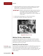
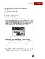
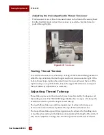
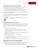
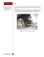
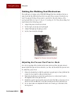
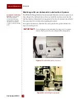
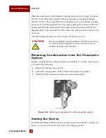
Facing the back of the sewing head, locate the screw at the top of the
machine, and the screw at the middle of the machine. These screws will
allow you to adjust the presser foot from front to back.
Linkage
An assembly of
parts linked together to
transmit motion.
6
Loosen the screws. While the two screws are loosened, you can manually
move the entire linkage from front to back.
7
After making the necessary adjustments, tighten the two screws.
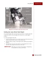
Setting the Top Feed and Presser Foot Height
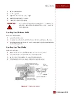
The measurement from the bottom of the presser foot to the top of the needle
plate should be 6.5–7 mm when the presser foot is in its highest position. To
achieve this setting, perform the following steps. See
to locate the
correct components.
Outer Guide
Places
pressure on the top feed
and the presser beam to
hold them against the
inner guide.
1
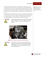
Remove the outer guide by removing the two socket head cap screws from
the outer housing.
2
Center the cap screw within the presser foot arm holder slot. Tighten the
screw.
3
Adjust the presser foot arm front to back as needed so that the presser foot
clears the needle bars in all positions of its travel.
4
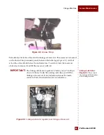
With the presser foot in its highest position, loosen the walking foot drive
crank screw, and manually move the drive crank up or down until the
desired setting of 6.5–7 mm is achieved.
5
Replace the crank screw and tighten it securely.
6
Tighten all screws. Manually rotate the handwheel clockwise. Verify that the
bottom of the presser foot to the top of the needle plate measures 6.5–7 mm.
Continue rotating the handwheel, making sure parts do not touch each other
in all positions of travel, including when the linkage is in its highest position.
7
Replace the outer guide with two or more shims provided.


