background image

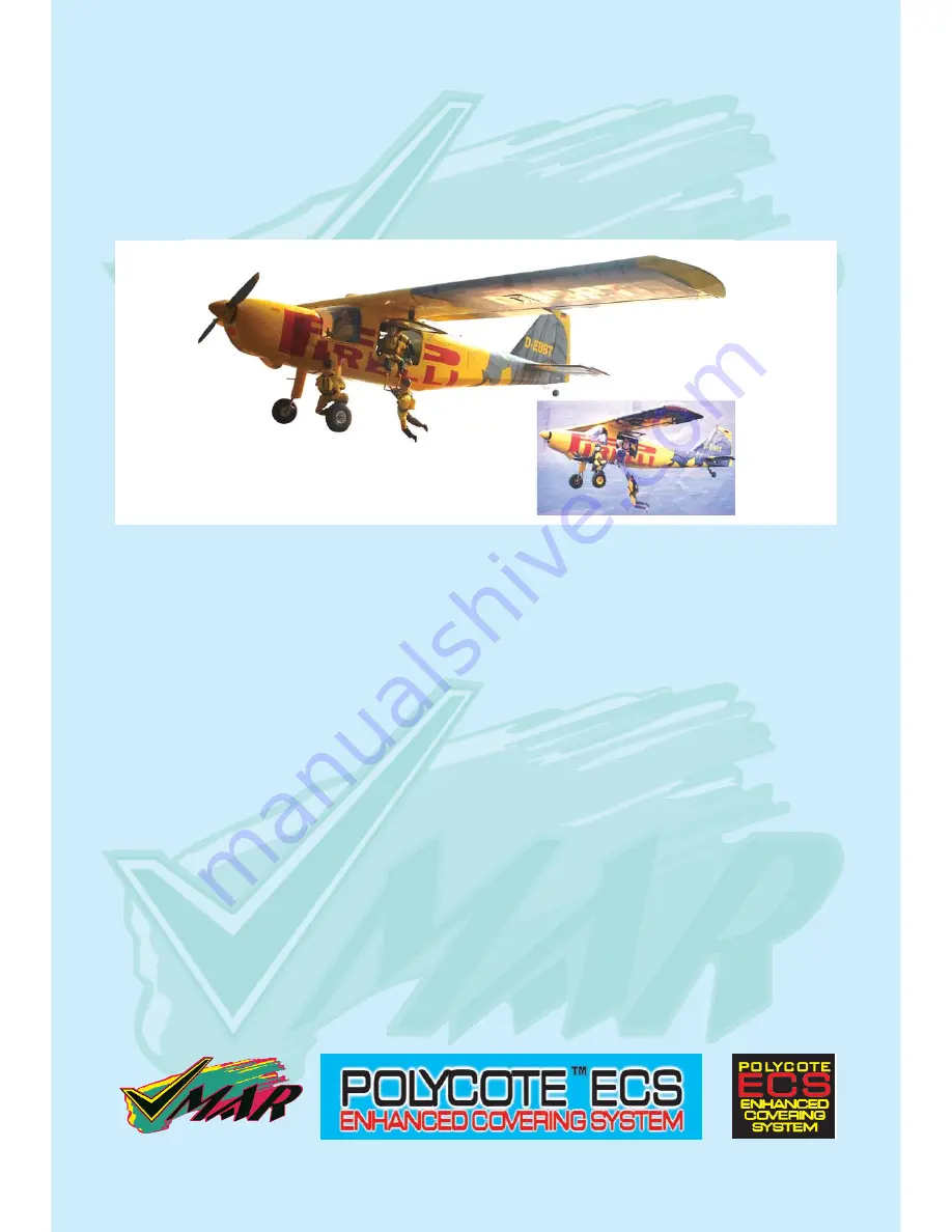
DORNIER DO 27

SEMI SCALE SPORT MODEL

Assembly

and

Operations Manual

Please review this manual throughly

Before assembling or Operating

The

DORNIER DO 27

Semi scale sport model

DORNIER DO 27

We’ve used our ULTRA TOUGH POLYCOTE ECS Enhanced Covering System

for this Model

TM

Содержание DORNIER DO 27

Страница 1: ...L Assembly and Operations Manual Please review this manual throughly Before assembling or Operating The DORNIER DO 27 Semi scale sport model DORNIER DO 27 We ve used our ULTRA TOUGH POLYCOTE ECS Enhanced Covering System for this Model TM ...

Страница 2: ... fit the aluminium wing joiners 1 4 Pushing slowly the aluminium wing joiner tubes to the second wing panel and slowly close the gap TM 1 1 Two aluminium wing joiner tubes and wing bolt clam set Wing joiner slots Wing bolt clam hole Center lines 1 3 Push two alu joiner tubes into the slots of the first wing pannel all the way to the center lines Center lines 1 5 Use wing bolt clam set to hold the ...

Страница 3: ...e wiring harness tubes at the aileron servo cavity end Install a servo in each aileron servo cavity and connect the servo wire to the servo extension wires and run the extension wires through wiring harness tubes to the centre of the wing Install the aileron control horns Aileron servos cavity 2 2 Aileron servos location 2 3 Aileron servos mount 2 4 Srew servo in position 2 5 Install aileron contr...

Страница 4: ...e up and viewed from the back ensure that moving the transmitter aileron stick to the left raises the left aileron and lowers the right aileron Movement of the stick to the left will roll the aircraft to the left Counterclockwise roll of the wing when viewed from the back Step 10 With the wing top side up and viewed from the back ensure that moving the transmitter aileron stick to the right raises...

Страница 5: ...uld look like this Vertical slot Horizontal slot 5 1 Horizontal stabilizers with pre installed elevator 5 3 Vertical stabilizers with pre installed rudder Check the fit of the horizontal stabilizer in its slot Make sure the tail is square and centred to the fuselage by taking measurements as shown in the dia grams on the right but don t glue any thing yet Equal distance Equal distance 900 6 1 Tria...

Страница 6: ...he film and not the wood otherwise the horizontal stabilizer wiil be severely weakened 8 1 Marked lines on horizontal stab 8 2 Cutting inside the lines 8 3 Removed covering from top surface 8 4 Exactly the same underneath 8 5 Clean off any traces of pen Now apply sufficient epoxy to the top and bottom of the horizontal stabilizer Use 30 minute epoxy to ensure a strong bond and give yourself plenty...

Страница 7: ...tip pen Now remove the vertical stabilizer using a sharp knife ruler CAREFULLY cut just 2mm inside the marked lines and remove the covering on both sides of the fin just as you did with the horizontal stabilizer making sure you only press hard enough to cut the covering not the vertical stabilizer Now apply sufficient epoxy to both sides and the bottom of the vertical stabilizer Use 30 minute epox...

Страница 8: ...6 or 1 6 mm drill bit 13 5 Mount the main landing gear fairing with 2x10 screw 13 6 Install the wheel 13 7 Install the main landing gear cover FITTING THE TAIL WHEEL 14 1 Insert the tail wheel steering wire into the steering guide tube 14 2 Screw the tail wheel assem bly to the fuselage 14 3 Trim off the excess tail steer ing wire Install the tail wheel assembly Note that the tail wheel assembly h...

Страница 9: ...ide the tank 15 3 Fuel tank installed on the power module 100 mm 4 in for fuel line 50 mm 2 in for pressure line fuel line pressure line INSTALLING THE ENGINE The engine and the fuel tank are installed onto the power module First remove the power module from the fuselage by removing the 4 nuts washers 16 1 Aluminum engine mount 16 2 Power module assembly 16 3 Engine thrust line Fuel tank holder do...

Страница 10: ...n 17 4 Elevator and rudder control horn connected to the contrrol rod 17 1 Control horn assembly Elevator control horn location INSTALLING THE SERVOS Install the rubber servo grommets and brass ferrules supplied with your radio equipment The three servos that control the elevator and rudder are Installed in the servo tray mounted in the fuselage Remove servo tray from the fuselage mounting the ser...

Страница 11: ...shrods to the control horns CONNECTING THE PUSHRODS TO THE RUDDER Connect the rudder servo to the receiver and turn on your transmit ter Confirm that the neutral posi tions of the rudder servo are sus tained as per illustration 22 4 21 1 Connecting the rudder pushrod to the rudder control horn Elevator servos Rudder servo Stick control rods CONNECTING THE THROTTLE CONTROL Connect the clevis to the...

Страница 12: ...s are in their neutral posi tions Check that the ailerons elevator and rudder are centred If any adjustments are needed do these by uncoupling the relevant clevis and turning it clockwise to shorten the linkage or couter clockwise to lenthen it Only when each control surface has been cen tred mechanically in this way should you begin adjusting the surface movement or throw FINAL R C SET UP ELEVATO...

Страница 13: ...em batteries and range testing the system before and after each flight 28 3 Check that all controls are working correctly before and after each flight The CG for your DO 27 is located at 95 to 100 mm 3 3 4 to 4 inch back from the leading edge of the wing when the wing has been attached to the fuselage For the initial flight the CG should be located at 3 3 4 95mm back from the leading edge of the w...

Страница 14: ...a third party who knows how to fly and how to set up a model air craft 30 3 Once you have completed your first flight get in the habit of checking your model over before and after each flight Don t fly if you find something that is not right Stage 30 CONFIRM MECHANICAL INTEGRITY Elevator Aileron Rudder 3 4 19mm 1 2 12 5mm CG Parts for this VMAR Model In the event that you require replacement parts...

Страница 15: ...from VMAR With POLYCOTE ECS the graphics are inside the covering not stuck on top No Decals No Layers No Strips No Stripes VMAR Models using POLYCOTE ECS have very few seams and our proprietary SURE SEAL system ensures that the seams stay down Best of all POLYCOTE itself is a totally fuel proof ULTRA TOUGH POLYESTER For more information Please visit our website www richmondrc com support htm DORNI...

Отзывы: