


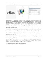
3. Construction
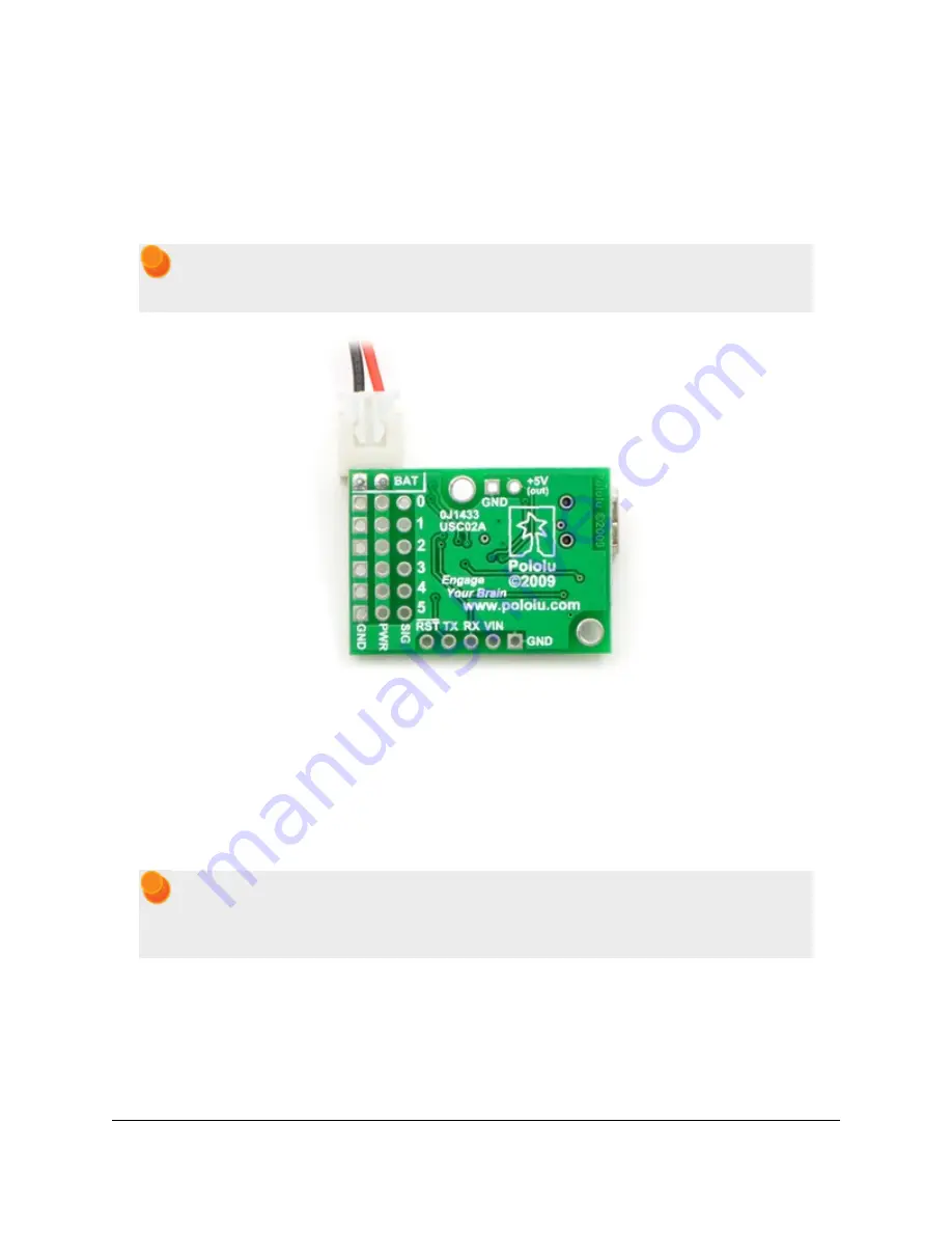
Step 1: Attach male header as a battery connector.
Find the 1×10 piece of 0.1" male header included with your Maestro. Break off a 1×2 piece and solder it to the
BAT and GND pins as shown. Note that the connector is not polarized, so you must be careful to always plug in
the battery with the
black
wire connected to ground and the
red
wire connected to BAT.
The connector shown in the picture is from an old version of the battery. The new one will look
different, but the black and red wires should still connect to the same pins on the Maestro.
Soldering a power connector to the Micro
Maestro.
Step 2: Set up the Maestro for self power.
With your battery
disconnected
, attach a wire (red) from the positive terminal of the male header to VIN. Take
care not to short or damage any of the components on the board. Now, with the battery plugged in, your Maestro
should be powered-up and slowly flashing its yellow LED, indicating that it is waiting to detect the baud rate
on the serial communication. You will not be using serial communication for this project, so you need to disable
baud rate detection in the next step.
The connector shown in the picture is from an old version of the battery. Since you will be using
male header, which completely covers the holes on the board, solder to the exposed part of the
header pin.
Sample Project: Simple Hexapod Walker
© 2001–2010 Pololu Corporation
3. Construction
Page 5 of 21