16
ENGLISH
14
!
ATTENTION:
verify that the return spring does not reach the
end of the stroke. Pull the rope completely and turn the wheel again
to check that it can make at least one turn before stopping.
This test is very important because the spring hasn’t been studied to
reach the end of the stroke and, if it happens, the spring will break.
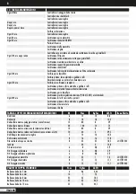
Reassemble the starter in the engine and tight the 4 screws (M5) with
strength (see the tightening torque values table).
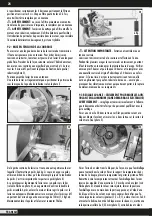
9.5 STARTER ROPE REPLACEMENT (STANDARD STARTER)
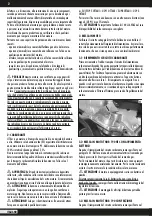
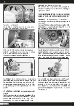
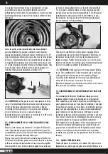
Remove the starter from the engine unscrewing the 4 screws (Photo
9). Remove the old rope. Be careful since the central wheel will turn
till the spring is completely discharged: keep it and discharge it slowly
to avoid damages or possible injuries. Prepare the new rope and tie
a knot at the top. Remove the old rope and keeping with a hand the
outside area, make the inside part rotate anticlockwise for 5 laps.
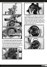
Stop it when the hole of the inside wheel is in correspondence of the
outside hole (photo 15).
15
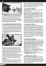
Now take the new rope and insert the head of the rope (the one
without knot) in both the holes simultaneously. Make the rope pass
completely till the knob reaches the end. Be careful not to release
the rope and let the spring pull the rope back and wind it up on the
internal wheel. Now make the free head of the rope pass through the
handle and make a simple but strong knob. (photo 14)
Reassemble the starter in the engine and screw the 4 M5 screws with
strength (see the tightening torque values table). Check the picklocks
wear and, if necessary, replace them unscrewing the central screw.
After replacing them tight the central screw again using medium
thread locker.
!
ATTENTION:
verify that the return spring does not reach the
end of the stroke. Pull the rope completely and turn the wheel again
to check that it can make at least one turn before stopping.
This test is very important because the spring hasn’t been studied to
reach the end of the stroke and, if it happens, the spring will break.
Reassemble the starter in the engine and screw the 4 screws (M5) with
strength (see the tightening torque values table).
10 HOW TO BEHAVE WHEN FLYING
Maximum acceleration is recommended only to take off (full power)
or when really necessary!
In order to avoid a poor mixture from acceleration/ascent to level
flight conditions, loosen the engine till a descending phase and then
gradually accelerate again till achieving a level flight or a glide
angle or a rise angle wished. In this way you will be sure to maintain
firm and efficient the carburation, avoiding being over rpm with a
minimum valve/throttle opening.
We remind you that two stroke engines do not stand constant range
for a long time too much. Take care of your engine by varying now
and then the rpm range. In this way the engine will have constant per-
formance and a good elasticity improving its working during the time.
10.1 TEMPERATURE THERESHOLDS
Your Thor engine, according to the pilot weight and wing size, must
have a flight temperature between 200° and 230° under sparkplug
(these measures have been taken with Polini thermocouple tool
– 928.830.002). This parameter may vary according to different
factors: environment temperature, working height, wet, and quality of
the fuel used, anyway this temperature has not to exceed 250°-260°.
Furthermore, it is important to say that carbon deposits caused by a
richer mixture may limit during the time the exceeding loss of heat,
favouring high temperatures that can compromise the reliability of the
engine. For these reasons we remind you to follow very carefully the
section concerning the servicing.
11- ENGINE FITTING ON THE FRAME
The engine is supplied in a packaging and it is screwed on a cage to
protect it during its carriage. Unscrew the 4 M8 screws that fix it and
extract the engine. KEEP THE PACKAGING AND ITS CAGE FOR POSSIBLE
REPARATIONS UNDER WARRANTY. WARRANTY IS NOT ACCEPTED IF THE
ENGINE IS NOT SHIPPED IN THE ORIGINAL PACKAGING. The engine
must be fixed on the frame using the 4 clamps with the silent-block to
be tightened using a torque wrench at 16 Nm.
Visit www.polinithor.com for the engine fixing measures.
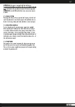
The filter has a hole at the top to be used to avoid its rotation when
using it. Place a clamp or a small cable (they are not provided with the
engine) fixing them in a proper area of the frame.
!
ATTENTION:
the filter may rotate if you do not fix it and it
could collide with the propeller, breaking it.
11.1 ENGINE WITH ELECTRIC STARTER
Firmly fix the battery that is supplied already charged (anyway we
suggest you should charge it one time before using it). Connect the
relay to the frame. Connect the two red cables to the battery positive
pole, the black cable to the negative pole while the yellow/green cable
must be connected to a NA switch (normally open) to earth that it is
necessary to switch the engine on.
Содержание THOR 190 HF
Страница 33: ......

