


4.39
ELECTRONIC FUEL INJECTION
4
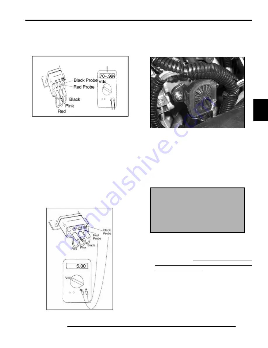
• Connect the test leads connected as shown in Figure 2
and the meter set to the “vdc” scale, move the throttle
open and closed slowly while reading the display. The
voltage should increase smoothly with no “jumps” or
decreases when the throttle is applied.
• If the TPS does not function correctly, replace it.
TPS Tester - Correct Reference Voltage
A 5 volt reference voltage signal from the test harness is
required for the TPS test to be accurate. Refer to the instructions
provided with the TPS Test Adapter Harness (
2201519
) or
follow these steps to check reference voltage.
• Harness Test: Insert black voltmeter probe into the
“Bk” test port.
• Connect the red meter probe into the “R” port and
verify the voltage is 4.99-5.01 vdc. If this reading is
low, verify the 9 volt battery is good or try a new 9 volt
battery.
Throttle Position Sensor Replacement
NOTE: The correct position of the TPS is
established and set at the factory. If the TPS is
repositioned, replaced or loosened it must be
recalibrated.
1. Remove the seat.
2. Disconnect sensor from the engine harness.
3. Loosen and rotate the throttle body (B) to gain access to the
retaining screws (if required).
4. Remove the retaining screws and replace the sensor, but do
not tighten the screws at this point.
5. Refer to “TPS Initialization” for setting the TPS voltage.
Throttle Position Sensor Initialization
Establishing a TPS setting :
This step is crucial as it sets the
TPS position using the fixed physical stop.
• Open and close throttle plate a couple of times to ensure
full throttle closing. Do not snap closed, as this could
cause unnecessary throttle plate to throttle body
interference and/or damage.
Tester 2201519
No “Jumps” in read out
The correct position of the throttle body idle
stop is established and set at the factory.
Do not loosen the throttle body idle stop or
alter the stop position in any fashion. If the
stop is repositioned, the entire throttle body
assembly must be replaced.
Содержание Ranger 500 2x4 2007
Страница 1: ......
Страница 7: ...1 5 GENERAL INFORMATION 1 VEHICLE DIMENSIONS 113 in 287 cm 58 in 147 cm 76 in 193 cm RANGER 2X4 4X4 ...
Страница 20: ...1 18 GENERAL INFORMATION SAE Tap Drill Sizes Metric Tap Drill Sizes Decimal Equivalents ...
Страница 82: ...3 23 ENGINE 3 Cylinder Head Exploded View EH50PL EFI Shown A A ...
Страница 153: ...4 45 ELECTRONIC FUEL INJECTION 4 Fuel Pump Circuit Ignition Coil Circuit ...
Страница 154: ...4 46 ELECTRONIC FUEL INJECTION Idle Air Control IAC Circuit Throttle Position Sensor TPS Circuit ...
Страница 155: ...4 47 ELECTRONIC FUEL INJECTION 4 Manifold Air Pressure Sensor MAP Circuit Engine Coolant Temperature Sensor Circuit ...
Страница 156: ...4 48 ELECTRONIC FUEL INJECTION Intake Air Temperature Sensor IAT Circuit Malfunction Indicator Light MIL Circuit ...
Страница 157: ...4 49 ELECTRONIC FUEL INJECTION 4 Diagnostic Connector Circuit ...
Страница 296: ...10 10 ELECTRICAL POWER DISTRIBUTION MODULE NON EFI MODELS PDM Operation ...
Страница 309: ...10 23 ELECTRICAL 10 EFI Cooling System Break Out Diagram PDM RD WH Key On 12 V Power ...
Страница 331: ...10 45 ELECTRICAL 10 ELECTRICAL BREAKOUT DIAGRAMS EFI MODELS Starting Circuit Key On Power Circuit ...
Страница 332: ...10 46 ELECTRICAL Transmission Switch Circuit Differential Solenoid Circuit ...
Страница 333: ...10 47 ELECTRICAL 10 Charging System Circuit Cooling Fan Circuit ...
Страница 334: ...10 48 ELECTRICAL AWD Circuit ...
Страница 339: ...WD 1 WIRE DIAGRAM RANGER 500 2X4 4X4 CHASSIS ...
Страница 340: ...WD 2 WIRE DIAGRAM RANGER 500 2X4 4X4 DASH ...
Страница 341: ...WD 3 WIRE DIAGRAM RANGER 500 EFI 4X4 CHASSIS PAGE 1 OF 2 ...
Страница 342: ...WD 4 WIRE DIAGRAM RANGER 500 EFI 4X4 CHASSIS PAGE 2 OF 2 ...
Страница 343: ...WD 5 WIRE DIAGRAM RANGER 500 EFI 4X4 DASH ...
Страница 344: ...WD 6 WIRE DIAGRAM RANGER 500 EFI 4X4 BREAKOUTS ...
Страница 345: ...WD 7 WIRE DIAGRAM RANGER 500 2X4 4X4 BREAKOUTS ...