


3.46
ENGINE
IMPORTANT: CAMSHAFT TIMING NOTE: In order to
time the camshaft to the crankshaft, the piston must
be precisely located at Top Dead Center (TDC).
Camshaft Timing
1. Apply Polaris Premium Starter Drive Grease (PN
2871460) to the camshaft main journals and cam lobes.
Lubricate automatic compression release mechanism with
clean engine oil. (To install the compression release
mechanism, refer to Page 3.21).
2. Install the camshaft with the lobes facing downward and the
sprocket alignment pin facing upward.
3. Disconnect the wire from the cam chain and rotate the
engine to align the single (TDC ) timing mark (Top Dead
Center) on the flywheel with the notch in the timing
inspection window. Be sure to use the single TDC mark
when installing the cam. Do not use the advance marks.
4. Loop the cam chain on the cam sprocket with the dots on
the sprocket facing outward and the alignment pin notch
facing directly upward.
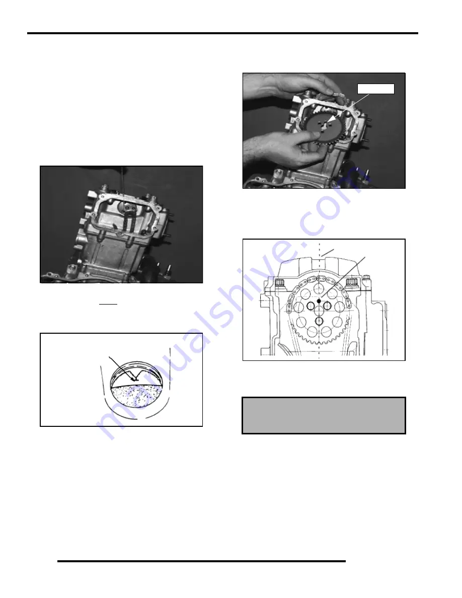
5. Before positioning the sprocket on the camshaft, check the
position of the cam sprocket alignment pin. When the cam
is positioned properly, the cam sprocket alignment pin (A)
is directly in line with the crankshaft / camshaft centerline
(B).
6. Install the sprocket on the camshaft. Apply Loctite™ 242
(PN 2871949)
to the cam sprocket bolts and torque to
specifications.
7. Verify TDC mark in timing inspection hole and alignment
pin is directly in line with crankshaft to camshaft centerline.
Refer to Illustration on the following page.
8. Apply Crankcase Sealant
(PN 2871557)
to the camshaft
end cap and install using a new O-Ring.
9. Check all cam timing marks to verify proper cam timing,
and install the cam chain tensioner body with a new gasket.
10. After tensioner installation, rotate engine at least two
revolutions and re-check marks/timing.
Single (TDC)
Mark Aligned
Cam Sprocket Bolt Torque:
6 ft. lbs. (8 Nm)
Pin Notch
A
B
Содержание Ranger 500 2x4 2007
Страница 1: ......
Страница 7: ...1 5 GENERAL INFORMATION 1 VEHICLE DIMENSIONS 113 in 287 cm 58 in 147 cm 76 in 193 cm RANGER 2X4 4X4 ...
Страница 20: ...1 18 GENERAL INFORMATION SAE Tap Drill Sizes Metric Tap Drill Sizes Decimal Equivalents ...
Страница 82: ...3 23 ENGINE 3 Cylinder Head Exploded View EH50PL EFI Shown A A ...
Страница 153: ...4 45 ELECTRONIC FUEL INJECTION 4 Fuel Pump Circuit Ignition Coil Circuit ...
Страница 154: ...4 46 ELECTRONIC FUEL INJECTION Idle Air Control IAC Circuit Throttle Position Sensor TPS Circuit ...
Страница 155: ...4 47 ELECTRONIC FUEL INJECTION 4 Manifold Air Pressure Sensor MAP Circuit Engine Coolant Temperature Sensor Circuit ...
Страница 156: ...4 48 ELECTRONIC FUEL INJECTION Intake Air Temperature Sensor IAT Circuit Malfunction Indicator Light MIL Circuit ...
Страница 157: ...4 49 ELECTRONIC FUEL INJECTION 4 Diagnostic Connector Circuit ...
Страница 296: ...10 10 ELECTRICAL POWER DISTRIBUTION MODULE NON EFI MODELS PDM Operation ...
Страница 309: ...10 23 ELECTRICAL 10 EFI Cooling System Break Out Diagram PDM RD WH Key On 12 V Power ...
Страница 331: ...10 45 ELECTRICAL 10 ELECTRICAL BREAKOUT DIAGRAMS EFI MODELS Starting Circuit Key On Power Circuit ...
Страница 332: ...10 46 ELECTRICAL Transmission Switch Circuit Differential Solenoid Circuit ...
Страница 333: ...10 47 ELECTRICAL 10 Charging System Circuit Cooling Fan Circuit ...
Страница 334: ...10 48 ELECTRICAL AWD Circuit ...
Страница 339: ...WD 1 WIRE DIAGRAM RANGER 500 2X4 4X4 CHASSIS ...
Страница 340: ...WD 2 WIRE DIAGRAM RANGER 500 2X4 4X4 DASH ...
Страница 341: ...WD 3 WIRE DIAGRAM RANGER 500 EFI 4X4 CHASSIS PAGE 1 OF 2 ...
Страница 342: ...WD 4 WIRE DIAGRAM RANGER 500 EFI 4X4 CHASSIS PAGE 2 OF 2 ...
Страница 343: ...WD 5 WIRE DIAGRAM RANGER 500 EFI 4X4 DASH ...
Страница 344: ...WD 6 WIRE DIAGRAM RANGER 500 EFI 4X4 BREAKOUTS ...
Страница 345: ...WD 7 WIRE DIAGRAM RANGER 500 2X4 4X4 BREAKOUTS ...