CLUTCH
6.24
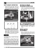
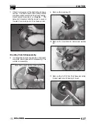
8. Remove nut (C) (left hand thread) from puller rod
and set aside.
9. Remove installation tool and clutch sheave from
puller.
LATE 2004 -- EBS DRIVEN
CLUTCH
DISASSEMBLY/INSPECTION -
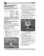
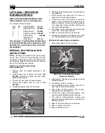
Late 2004 EBS Driven Clutch Operation
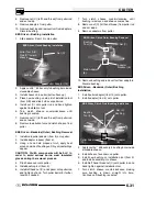
The late model EBS driven clutch provides the same
engine braking abilities as the earlier EBS driven
clutch.
One--way Clutch
Drive Clutch
Belt Rotation
Downhill
Drive
Driven
Stop Plate
When the ATV is moving downhill the drive train turns
the driven clutch, belt, and one way clutch in the
direction of engine rotation. When the one--way
clutch (see exploded view of drive clutch) exceeds the
drive clutch rotational speed, the one--way clutch
locks to the drive clutch shaft and engine braking
occurs. Essentially the driven clutch has become the
“driving” clutch. The stop plate (bow plate) that is fixed
to the transmission shaft rotates in the pocket of the
sheave, allowing the stationary sheave to rotate with
the moveable sheave as the rollers move to the other
side of the ramp, providing instant EBS braking.
Engine braking (EBS) continues until the drive clutch
speed exceeds the one--way clutch speed, or until the
throttle is applied and the engine reaches clutch
engagement speed, lifting the belt off of the one--way
clutch.
CAUTION:
The
driven
clutch
must
be
disassembled from the helix end to reduce spring
pressure. Review all information below before
proceeding.
DRIVEN DISASSEMBLY/ASSEMBLY
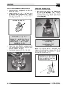
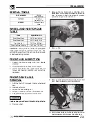
1. Remove driven clutch from the transmission input
shaft. Do not attempt disassembly of the driven
clutch from the outside snap ring. The driven
clutch must be disassembled from the helix side
or the one-way clutch seals may be damaged.
Do not disassemble from this side
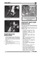
2. It is important to mark the position of the shaft,
stop plate, and sheave before disassembly. Mark
the helix and inside sheave also. This will aid in
reassembly.
Содержание 600 Dragon SP
Страница 1: ...2004 SPORTSMAN 600 700 SERVICE MANUAL PN 9918803 ...
Страница 138: ...BODY STEERING SUSPENSION 5 16 NOTES ...
Страница 210: ...FINAL DRIVE 7 38 NOTES ...
Страница 293: ...ELECTRICAL 10 43 WIRING DIAGRAM HAND AND THUMB WARMERS WINCH HUNTER EDITION ...
Страница 294: ...ELECTRICAL 10 44 NOTES ...
Страница 295: ...ELECTRICAL WIRING DIAGRAM EARLY 2004 SPORTSMAN 600 700 BUILT BEFORE FEB 20 2003 Built Before February 20 2003 ...
Страница 297: ...ELECTRICAL WIRING DIAGRAM LATE 2004 SPORTSMAN 600 700 BUILT AFTER FEB 20 2003 Built After February 20 2003 ...
Страница 298: ...ELECTRICAL WIRING DIAGRAM LATE 2004 SPORTSMAN 600 700 BUILT AFTER FEB 20 2003 Built After February 20 2003 NOTES ...
Страница 299: ...ELECTRICAL WIRING DIAGRAM LATE 2004 SPORTSMAN 600 700 MODELS WITH FUEL GAUGE Models Equipped with Fuel Gauge ...
Страница 300: ...ELECTRICAL WIRING DIAGRAM LATE 2004 SPORTSMAN 600 700 MODELS WITH FUEL GAUGE NOTES ...
Страница 301: ...ELECTRICAL WIRING DIAGRAM 2004 SPORTSMAN 600 700 HUNTER EDT HAND WARM WINCH ...
Страница 307: ...Winch Switch Installation 10 34 Winch Wiring 10 35 Wiring Diagram Hand Thumb Warmer Winch 10 43 ...
Страница 308: ...PN 9918803 Printed in USA ...


