


CLUTCH
6.8
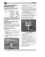
PVT ASSEMBLY/INSPECTION
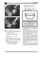
1. Inspect PVT inner cover-to-engine seal. Replace
if cracked or damaged. Align the alignment mark
on the cover with the mark on the engine seal.
Seal this edge to cover on engine side
2. Place a new seal on transmission input shaft.
3. Apply RTV silicone sealant to outside edge of
inner cover-to-engine seal, to ensure a water tight
fit between the seal and the cover on engine side.
Surfaces must be clean to ensure adhesion of
silicone sealant.
4. Reinstall cover and tighten rear cover bolts just
enough to hold it in place.
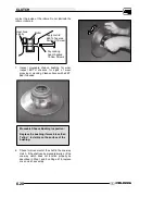
5. Fit lip of inner cover seal (A) to engine. Install seal
retainer plate and tighten screws securely.
6. Torque rear inner cover bolts (B) to specification.
Seal outer edge to cover
with RTV silicone sealant
A
B
C
Inner Cover Bolt Torque (Rear):
12 ft. lbs. (16.6 Nm)
Driven Clutch Retaining Bolt Torque:
17 ft. lbs. (23.5 Nm)
Drive Clutch Retaining Bolt Torque:
40 ft. lbs. (55 Nm)
7. Install clutch offset spacer(s) on transmission
input shaft.
Offset
Spacer
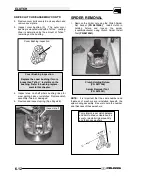
8. Clean splines inside driven clutch and on the
transmission input shaft.
9. Apply a light film of grease to the splines on the
shaft.
10. Install the driven clutch, washer, lock washer, and
retaining bolt. Torque to specification.
11. Clean end of taper on crankshaft and the taper
bore inside drive clutch.
12. Install drive clutch and torque retaining bolt to
specification.
13. Reinstall drive belt noting direction of rotation. If a
new belt is installed, install so numbers can be
easily read.
14. Only replace PVT outer cover rubber gasket if it is
damaged. Place the gasket with the narrow side
out (C).
PVT Cover Gasket
Toward outer cover
15. Reinstall PVT outer cover and secure with
screws.
16. Reinstall rear cab assembly, panel and seat.
Содержание 600 Dragon SP
Страница 1: ...2004 SPORTSMAN 600 700 SERVICE MANUAL PN 9918803 ...
Страница 138: ...BODY STEERING SUSPENSION 5 16 NOTES ...
Страница 210: ...FINAL DRIVE 7 38 NOTES ...
Страница 293: ...ELECTRICAL 10 43 WIRING DIAGRAM HAND AND THUMB WARMERS WINCH HUNTER EDITION ...
Страница 294: ...ELECTRICAL 10 44 NOTES ...
Страница 295: ...ELECTRICAL WIRING DIAGRAM EARLY 2004 SPORTSMAN 600 700 BUILT BEFORE FEB 20 2003 Built Before February 20 2003 ...
Страница 297: ...ELECTRICAL WIRING DIAGRAM LATE 2004 SPORTSMAN 600 700 BUILT AFTER FEB 20 2003 Built After February 20 2003 ...
Страница 298: ...ELECTRICAL WIRING DIAGRAM LATE 2004 SPORTSMAN 600 700 BUILT AFTER FEB 20 2003 Built After February 20 2003 NOTES ...
Страница 299: ...ELECTRICAL WIRING DIAGRAM LATE 2004 SPORTSMAN 600 700 MODELS WITH FUEL GAUGE Models Equipped with Fuel Gauge ...
Страница 300: ...ELECTRICAL WIRING DIAGRAM LATE 2004 SPORTSMAN 600 700 MODELS WITH FUEL GAUGE NOTES ...
Страница 301: ...ELECTRICAL WIRING DIAGRAM 2004 SPORTSMAN 600 700 HUNTER EDT HAND WARM WINCH ...
Страница 307: ...Winch Switch Installation 10 34 Winch Wiring 10 35 Wiring Diagram Hand Thumb Warmer Winch 10 43 ...
Страница 308: ...PN 9918803 Printed in USA ...


