


BODY / STEERING / SUSPENSION
5.11
A-ARM REPLACEMENT
1. Elevate and safely support vehicle with weight
removed from front wheel(s). Remove wheels.
2. Remove cotter pin from ball joint stud at wheel
end of A-arm and loosen nut until it is flush with
end of stud.
3. Using a soft face hammer, tap nut to loosen A-arm
from bolt. Remove nut and A-arm from hub strut
assembly.
4. Loosen two bolts on A-arm tube by alternating
each about 1/3 of the way until A-arm can be
removed.
5. Examine A-arm shaft. Replace if worn. Discard
hardware.
6. Insert A-arm shaft into new A-arm.
7. Install CV joint shields.
8. Install new A-arm assembly onto vehicle frame.
Torque new bolts to 30 ft. lbs. (41.4 Nm).
WARNING
The locking features on the existing bolts were
destroyed during removal.
DO NOT
reuse old bolts.
Serious injury or death could result if fasteners come
loose during operation.
A-arm Attaching Bolt Torque:
30 ft. lbs. (41 Nm)
Ball Joint Stud Nut Torque:
25 ft. lbs. (35 Nm)
9. Attach A-arm to hub strut assembly. Tighten ball
joint nut to 25 ft. lbs. (35 Nm). If cotter pin holes
are not aligned, tighten nut slightly to align. Install
a new cotter pin with open ends toward rear of
machine. Bend both ends in opposite directions
around nut.
WARNING
Upon A-arm installation completion, test vehicle at
low speeds before putting into regular service.
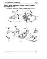
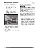
Vehicle Frame
Nut
Cotter Pin
Ball Joint
Stud
CV Joint Shield
A-Arm Tube
A-Arm Shaft
Bolt 30 ft. lbs.
(41 Nm)
Washer
25 ft. lbs
(35 Nm).
8 ft. lbs.
(11 Nm)
Bolt 30 ft. lbs.
(41 Nm)
Apply Loctite
t
242 to
the bolt threads.
242
242
Bushing
Содержание 600 Dragon SP
Страница 1: ...2004 SPORTSMAN 600 700 SERVICE MANUAL PN 9918803 ...
Страница 138: ...BODY STEERING SUSPENSION 5 16 NOTES ...
Страница 210: ...FINAL DRIVE 7 38 NOTES ...
Страница 293: ...ELECTRICAL 10 43 WIRING DIAGRAM HAND AND THUMB WARMERS WINCH HUNTER EDITION ...
Страница 294: ...ELECTRICAL 10 44 NOTES ...
Страница 295: ...ELECTRICAL WIRING DIAGRAM EARLY 2004 SPORTSMAN 600 700 BUILT BEFORE FEB 20 2003 Built Before February 20 2003 ...
Страница 297: ...ELECTRICAL WIRING DIAGRAM LATE 2004 SPORTSMAN 600 700 BUILT AFTER FEB 20 2003 Built After February 20 2003 ...
Страница 298: ...ELECTRICAL WIRING DIAGRAM LATE 2004 SPORTSMAN 600 700 BUILT AFTER FEB 20 2003 Built After February 20 2003 NOTES ...
Страница 299: ...ELECTRICAL WIRING DIAGRAM LATE 2004 SPORTSMAN 600 700 MODELS WITH FUEL GAUGE Models Equipped with Fuel Gauge ...
Страница 300: ...ELECTRICAL WIRING DIAGRAM LATE 2004 SPORTSMAN 600 700 MODELS WITH FUEL GAUGE NOTES ...
Страница 301: ...ELECTRICAL WIRING DIAGRAM 2004 SPORTSMAN 600 700 HUNTER EDT HAND WARM WINCH ...
Страница 307: ...Winch Switch Installation 10 34 Winch Wiring 10 35 Wiring Diagram Hand Thumb Warmer Winch 10 43 ...
Страница 308: ...PN 9918803 Printed in USA ...


