


7.17
FINAL DRIVE/BRAKES
7
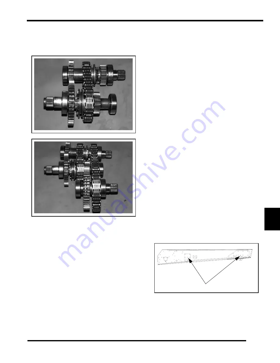
Transmission Assembly
Lubricate all parts before assembly with Premium Synthetic
Chaincase Lubricant.
1.
Install chain on input and reverse shaft.
2.
Add output gear assembly with chain.
3.
Add shift fork assembly.
4.
Install entire assembly in case half.
5.
Apply 3 Bond™ 1215 Sealant to case halves.
6.
Install outer case half and replace brake cable bracket.
Torque bolts in three steps to 8-10 ft. lbs. (11-14 N-m) using
a criss-cross pattern. Remove dowel from tensioner and
install access plug (where applicable).
7.
Install seals, shift arm, brake disc and caliper. Install
detente ball, spring, and spring guide. Fill with 20 ounces
(600cc) Polaris Premium Synthetic 0W-40 Oil.
Transmission Installation
1.
Tip unit onto right side.
2.
Insert track in unit, making sure direction of rotation is
correct.
3.
Place drive shaft in unit, aligning drive sprockets and track
drive lugs.
4.
Install lock collar, flangette, bearing, gasket, and flangette
on drive shaft, positioning bearing flush with end of drive
shaft.
5.
Lightly tighten set screws to hold bearing in place.
6.
Align flangette holes with tunnel.
7.
Replace adaptor key in drive shaft. Install angle drive
housing aligning adaptor key with angle drive.
8.
Install nuts and finger tighten.
9.
Tip machine onto its left side.
10. Replace O-rings on input and output shafts. Apply Polaris
All Season Grease to drive shaft coupler splines.
11. Reinstall transmission, using care not to damage coolant
hoses. Be sure transmission shift linkage is properly
located.
12. Install lower front mounting bolt (3) before coupling to
shaft. Once bolt is started into transmission housing, align
coupling with drive shaft and jack shaft splines. Keep
transmission flat and lower gradually to prevent binding of
couplers.
13. Install remaining transmission mounting bolts. Reinstall
shim washers in original positions and tighten bolts
securely.
NOTE: Proper transmission/jackshaft alignment is
critical for bearing service life. Use a standard nut
and flat washer for initial installation of
transmission, and install new mounting hardware
after jackshaft alignment is complete.
14. Tip machine onto its right side.
15. Loosen set screws and seat drive shaft in transmission
coupler stub shaft. For ease of assembly, make sure track
has no pressure against drive shaft.
16. Tighten nuts retaining angle drive housing to tunnel.
Torque to specification.
17. Reinstall suspension inside track and align with tunnel
mounting holes.
18. Install and hand tighten suspension bolts (1).
19. Install front carrier shaft assembly inside track and mount
to tunnel with bolts. Hand tighten bolts.
20. Install rear carrier shaft assembly. Make sure bolts are not
cross threaded and hand tighten.
21. Tip machine back onto floor and tighten all suspension
bolts to specification.
1
Содержание 340 LX 2007
Страница 4: ......
Страница 40: ...NOTES MODEL SPECIFICATIONS 1 36...
Страница 51: ...2 11 GENERAL 2 SPECIAL TOOLS Special Tools...
Страница 52: ...2 12 GENERAL...
Страница 53: ...2 13 GENERAL 2...
Страница 54: ...2 14 GENERAL...
Страница 80: ...NOTES MAINTENANCE 3 26...
Страница 91: ...4 11 FUEL DELIVERY 4 Throttle Opening Vs Fuel Flow VM only...
Страница 104: ...NOTES FUEL DELIVERY 4 24...
Страница 114: ...5 10 ENGINE 500 600 Touring WideTrak LX Touring WideTrak...
Страница 146: ...NOTES ENGINE 5 42...
Страница 170: ...NOTES CLUTCHING 6 24...
Страница 214: ...NOTES FRONT SUSPENSION STEERING 8 20...
Страница 259: ...10 11 CHASSIS HOOD 10...
Страница 260: ...NOTES CHASSIS HOOD 10 12...
Страница 272: ...11 12 BATTERY ELECTRICAL SYSTEMS ELECTRIC START GEN II EDGE System Schematic...
Страница 276: ...11 16 BATTERY ELECTRICAL SYSTEMS ELECTRIC START IQ CARBURETED CFI System Schematic 600 HO Carbureted...
Страница 277: ...11 17 BATTERY ELECTRICAL SYSTEMS 11 System Schematic 600 700 CFI...
Страница 286: ...11 26 BATTERY ELECTRICAL SYSTEMS Chassis Relay...
Страница 288: ...11 28 BATTERY ELECTRICAL SYSTEMS Vehicle Speed Sensor...
Страница 293: ...11 33 BATTERY ELECTRICAL SYSTEMS 11 CFI Power System CFI Ignition Injection Power...
Страница 294: ...11 34 BATTERY ELECTRICAL SYSTEMS CFI Crank Position System CFI Safety Stop System...
Страница 295: ...11 35 BATTERY ELECTRICAL SYSTEMS 11 CFI Full Load Fuel Injectors CFI Part Load Fuel Injectors...
Страница 296: ...11 36 BATTERY ELECTRICAL SYSTEMS CFI Chassis Power CFI Ignition Coils...
Страница 297: ...11 37 BATTERY ELECTRICAL SYSTEMS 11 CFI TBAP Sensor CFI TPS Engine Temp Sensors...
Страница 298: ...11 38 BATTERY ELECTRICAL SYSTEMS CFI Exhaust Solenoid CFI Knock Sensor...
Страница 299: ...11 39 BATTERY ELECTRICAL SYSTEMS 11 CFI Fuel Pump CFI Diagnostic Connections...
Страница 300: ...11 40 BATTERY ELECTRICAL SYSTEMS CFI MFD Circuits CFI MFD Power Circuits...
Страница 301: ...11 41 BATTERY ELECTRICAL SYSTEMS 11 CFI Fuel Level Circuit CFI Vehicle Speed Circuit...
Страница 302: ...11 42 BATTERY ELECTRICAL SYSTEMS CFI Mode Set Switch CFI PERC Switch...
Страница 318: ...12 1 Wiring Diagrams 2007 340 550 GEN II EDGE Models...
Страница 319: ...12 2 Wiring Diagrams 2007 Wide Trak...
Страница 320: ...12 3 Wiring Diagrams 2007 500 XCSP...
Страница 321: ...12 4 Wiring Diagrams 2007 600 HO Carbureted 1 of 2...
Страница 322: ...12 5 Wiring Diagrams 2007 600 HO Carbureted 2 of 2...
Страница 323: ...12 6 Wiring Diagrams 2007 600 HO Carbureted Hood Harness...
Страница 324: ...12 7 Wiring Diagrams 2007 600 700 CFI 1 of 2...
Страница 325: ...12 8 Wiring Diagrams 2007 600 700 CFI 2 of 2...
Страница 327: ...12 10 Wiring Diagrams...


