ENG
12
1.5.
START-UP
1.
Check that the installation has been carried out properly.
2.
Open the water inlet tap previously connected to a ¾ ”outlet, feed water with a flow of 60 L / H for
10DESA0041 and 10DESA1041. The flow should be 80 L / H for the 10DESA0081 stills; and 100
L / H for 10DESA0120.
3.
Turn switch S to the ON position. The green light will come on and after about 10 minutes the
distillation process will begin.
1.6. MAINTENANCE
1.
With the switch in the OFF position; and the power cable disconnected from the mains remove
the refrigerant.
2.
Pour in hydrochloric acid, strong water, or hot water until it comes out of the drain. Leave on
for 15 minutes.
3.
Pour all liquid and impurities into a drainpipe.
4.
Rinse with plenty of water.
5.
Repeat steps 2, 3 and 4 if necessary.
6.
Carry out a distillation that must be discarded.
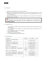
1.7. SPARE PARTS
Description
Symbol
Cat. Number
Qty.
Contactor, 230 V (10DESA0041 y
10DESA0081)
C1
YE.DCONT00011
1
Contactor, 230 V (10DESA0120)
C1
YE.DCONT00010
1
Contactor, 110 V (10DESA1041)
C1
YE.DCONT10001
1
Thermostat
T
YE.DTERM00001
1
Heater, 110 V (10DESA1041)
R
YE.DRDES00110
1
Heater, 230 V (10DESA0041 - 10DESA0081)
R - R1,R2
YE.DRDES00220
1 - 2
Heater, 230 V (10DESA0120)
R1, R2,
R3
0100721552
3
Silicone gasket (10DESA0081 y 10DESA0120)
---
YP.DJUSD00075
1
Silicone gasket (10DESA0041 y 10DESA1041)
---
YP.DJUSD00035
1
Plastic switch level
N
YE.DSONI00001
1
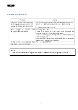
Warning: Always disconnect the power supply before carrying out the
cleaning operation
Содержание DESA 0041
Страница 7: ...ESP 6 1 9 DIAGRAMA ELECTRICO ...
Страница 8: ...ESP 7 ...
Страница 9: ...ESP 8 ...
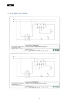
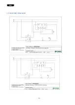
Страница 15: ...ENG 14 1 9 ELECTRIC DIAGRAM ...
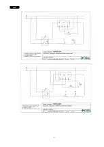
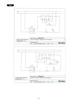
Страница 16: ...ENG 15 ...
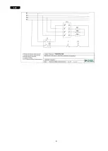
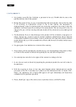
Страница 17: ...ENG 16 ...


