12
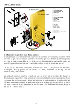
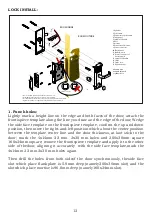
LOCK INSTALL:
ROOM INSIDE
1. Cylinder
2. Pcb reader
3.
4.
Connector of pcb reader
Front panel
5. Spindle of handle
6. Door
7. Mortise
8.
9.
Connector of mortise
10. Back panel
11.
Power connector
12.
Battery-pack
13. Spindle of handle
14.
Power connector of
battery-pack
Strike
15.
16.
Strike box
handle hole
a.
Cylinder cover
b. thumb turn hole
cylinder hole
c.
2
4
16
3
5
11
12
13
14
15
BATTERY
BATTERY
BATTERY
BATTERY
10
9
8
7
b
c
a
a’
b’
c’
*
ROOM OUTSIDE
*
*
This is a standard right lever lock. The left is in reverse case.
Model K2S mortise requires
door thickness at least 40.0mm.
*
For other thickness door please contact with us seeking other mortise solution
11
6
Right for the hardware configuration changes without notice is reserved.
arrow horizontal
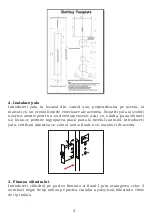
1. Punch holes:
Lightly mark a height line on the edge and both faces of the door, attach the
frontispiece template along the line you draw and the edge of the door; Wedge
the side face template on the frontispiece template, confirm the up and down
position, then move the right-and-left position which about the center position
between the template center line and the door thickness, at last stick to the
door; mark the 4x14mm 22 mm 2x30 mm holes and 200x30mm square
160x24mm square; remove the frontispiece template and apply it to the other
side of thedoor, aligning it accurately with the side face template,mark the
4x14mm 22 mm 2x30 mm holes again.
Then drill the holes from both sideof the door synchronously, theside face
slot which place flankplate is 5.0mm deep (namely200x30mm slot) and the
slotwhich place mortise is96.0mm deep (namely160x24mm slot).


