


30.2
Sampling intervals
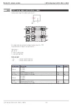
The table opposite shows the sampling intervals for conversion
of the input signals into internal values and conversion of the
internal values into output signals (hardware conversion).
The sampling interval for software calculation of function
blocks AINP1, AINP3...AINP6, DINPUT, STATUS, CONST, LED,
INFO, OUT1...OUT5 and DIGOUT is 100 ms.
Input or output
Sampling interval
INP1
at intervals of 200 ms
INP3 / INP4
at intervals of 100 ms
INP5
at intervals of 800 ms
INP6
at intervals of 400 ms
di1...di12
at intervals of 100 ms
OUT1...OUT5 / do1...do6 at intervals of 100 ms
Calculation of the other
function blocks is at equal
intervals according to their alloca-
tion to the 8 time slots of 100 ms
each.
Allocation of a block to one or
several time slots (at intervals of
100, 200, 400 or 800 ms) is in the
engineering. For each block, the en-
gineering tool provides an identifi-
cation (ts) which can be used to
determine the allocation from the
table opposite.
The total of calculation times of all
required function blocks must be <
100 % for each time slot.
30.3
EEPROM data
Data are stored in non-volatile EEPROM. The manufacturers specify approx. 100 000 permissible write/read cycles per
EEPROM address, in reality, however, this value can mostly be exceeded by a multiple. If parameters and configura-
tions are changed exclusively manually, exceeding the max. number of write/read cycles is almost precluded. With dig-
ital interface or automatic parameter changes, however, taking the maximum number of write/read cycles into account
is indispensable, and measures against excessively frequent parameter writing must be take
Function management
9499 040 50611
Sampling intervals
238
Time slot
ts
1 2 3 4 5 6 7 8 Sampling interval
11
f f f f f f f f
at intervals of 100 ms
21
f
f
f
f
at intervals of 200 ms
22
f
f
f
f
at intervals of 200 ms
31
f
f
at intervals of 400 ms
32
f
f
at intervals of 400 ms
33
f
f
at intervals of 400 ms
34
f
f
at intervals of 400 ms
41
f
at intervals of 800 ms
42
f
at intervals of 800 ms
43
f
at intervals of 800 ms
44
f
at intervals of 800 ms
45
f
at intervals of 800 ms
46
f
at intervals of 800 ms
47
f
at intervals of 800 ms
48
f
at intervals of 800 ms
Содержание KS 98
Страница 8: ...Description 9499 040 50611 Construction 8...
Страница 10: ...Important technical data 9499 040 50611 Further external in and outputs 10...
Страница 12: ...Versions 9499 040 50611 I O modules for units with modular option c basic card 12...
Страница 14: ...Front view 9499 040 50611 14...
Страница 16: ...Mounting 9499 040 50611 16...
Страница 26: ...Maintenance 9499 040 50611 Further information 26...
Страница 36: ...Scaling and calculating functions 9499 040 50611 LG10 10s logarithm 36...
Страница 74: ...Signal converters 9499 040 50611 MEAN mean value formation 74...
Страница 128: ...KS98 I O extensions with CANopen 9499 040 50611 RM_DMS strain gauge module 128...
Страница 132: ...CSEND Send mod blockno s 21 23 25 27 No 57 132...
Страница 140: ...Description of KS98 CAN bus extension 9499 040 50611 140...
Страница 202: ...Controller 9499 040 50611 Process value calculation 202...


