


28
KS98 I/O extension modules
Can be used in KS98: 9407 - 9xx - x
3
xx1 and 9407 - 9xx - x
4
xx1.
Safety hints
l
ESD !
w
Contains electrostatically sensitive components
w
Original packaging protects against electrostatic discharge (ESD)
w
Transport only in the original packaging
w
During mounting, follow the rules for protection against ESD.
Connection
:
Note the KS98 engineering! It determines the allocation of connector positions and the signification of connections.
Maintenance:
The instruments do not require any particular maintenance.
a
When opening the instruments, live parts may be exposed. The instruments must be completely de-energized
before any work is done. The instruments contain electrostatically sensitive components.
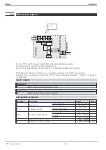
I/O modules
9407 - 998 -
00
xx1
Module type:
Analog inputs:
Pt 100 / 1000, Ni 100 /1000,
20
Resistance , potentiometer
Thermocouple, mV, 0/4..20mA
21
-50...1500mV, 0...10V
22
Analog outputs:
1)
0/2...10V, 0...
_
10V
30
0/4...20mA, 0...
_
20mA
31
Digital inputs/output:
Digital I/O (universal)
40
Frequency/counter
41
The various modules
are distinguished
by label inscription.
The 5 last digits of the order number
are given in the upper line.
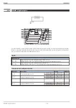
Mounting
After releasing the locking screw, withdraw the
KS98 module from the housing. (
a
) - Insert the
module into the required socket
with the
printed label pointing downwards into the green
connector and click it in position in the small,
white contact (
b
) at the top.
(70) (69) (68) (67)
(Block-No.)
4
3
2 1
Slot
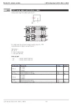
2)
1)
PERFORMANCE LIMITS
Due to the maximum permissible self-heating, the number of analog output modules per KS98 is limited:
max. one current output module! Max.one voltage output module, if there is already a current output module (but in different, galvani-
cally isolated module groups)! The total of performance factors (P-factor,
r
Technical data must not exceed 100% ! Exceeded perfor-
mance limits are displayed in the engineering tool. Unless a current output module is used, all sockets can be provided with any
modules. Max. 1 current output module (on any socket)! Max 1 current and max. 1 voltage output module, but on galvanically isolated
sockets!
Example
:
current output module on slot 1 or 2 and voltage output module on slot 3 or 4.
The total of P factors is 95%. I.e. 1 more resistance or 1 TC/mV/mA module can be fitted.
2)
Galvanic isolation:
Slots 1-2 are galvanically isolated from 3-4.
9499 040 50611
KS98 I/O extension modules
225
00201
R_Inp
8368
Содержание KS 98
Страница 8: ...Description 9499 040 50611 Construction 8...
Страница 10: ...Important technical data 9499 040 50611 Further external in and outputs 10...
Страница 12: ...Versions 9499 040 50611 I O modules for units with modular option c basic card 12...
Страница 14: ...Front view 9499 040 50611 14...
Страница 16: ...Mounting 9499 040 50611 16...
Страница 26: ...Maintenance 9499 040 50611 Further information 26...
Страница 36: ...Scaling and calculating functions 9499 040 50611 LG10 10s logarithm 36...
Страница 74: ...Signal converters 9499 040 50611 MEAN mean value formation 74...
Страница 128: ...KS98 I O extensions with CANopen 9499 040 50611 RM_DMS strain gauge module 128...
Страница 132: ...CSEND Send mod blockno s 21 23 25 27 No 57 132...
Страница 140: ...Description of KS98 CAN bus extension 9499 040 50611 140...
Страница 202: ...Controller 9499 040 50611 Process value calculation 202...


