Plumis Automist Smartscan Скачать руководство пользователя страница 34

Automist Smartscan

®

 Handbook v1.2.3 


Plumis Ltd Copyright © 2017. All Rights Reserved. 


Page 34 of 64 


S MA RT SC AN

®

A) Preparing the site 

Important!

 Connecting the system to the mains requires a competent electrician with 17th Edition 

Electrical Qualifications. The Automist Smartscan circuit should be clearly labelled (a sticker is provided for 
this purpose). Automist Smartscan requires an independent 230V a.c. / 50Hz electrical supply, not shared 
with other unrelated devices. Components of the fire detection and alarm system may use this circuit, 
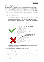
which must remain powered in the event of a fire. Power to Automist Smartscan must be provided via an 
unswitched fused connection unit (FCU). Automist Smartscan should be supplied using FP200 cable or 
better, ideally inside conduit or protected 50mm deep within a wall, and with no RCD or RCBO protection. 
RCD or RCBO protection may be required, however, by applicable electrical installation regulations, in which 
case the circuit design must be such that the operation of any other RCD, RCBO or safety device does not 
affect the operation of Automist Smartscan. Typically, on a split-load board, Automist Smartscan should be 
connected to the non-protected side of the board. Where there are no spare ways in the existing consumer 
unit, or there are no available non-RCD protected ways in the existing consumer unit, the electrician may 
wish to use a Henley Block to provide new tails to a second distribution board (typically a 2- or 4-way unit). 

The Automist Smartscan unit presents a part-inductive load and therefore only t

ype “C” 

breakers are 

suitable. Because Automist Smartscan is often used for life safety applications, installers should add a 
suitable safety margin to the MCB ratings. The circuit supplying a single Automist Smartscan unit would 

commonly be protected by a type ‘C10’ or ‘

C

16’, for example, or ‘C20’ / ‘

C32

’ for two 

Automist Smartscan 

units. This should be on a C-type breaker, on an RCBO or a RCD protected circuit. The RCD circuit should 
protect only the Automist Smartscan system and not be incorporated with any other circuit in the property. 
If the consumer unit is located in the protected area it should be protected by an electrical cover. However, 
if the consumer unit is in the protected area and has a metal enclosure complying with 17th Edition IET 
Wiring Regulations to BS 7671 2008; Amendment 3, it does not require the addition of an over box to meet 
BS476 Part 22 (1987) and EN1364 (1999) which pre-dates Amendment 3 becoming effective. If the electrical 
installation is required to follow BS 8458, the stipulations of that standard should be adopted; in particular 
it may require the use of fuses rather than MCBs as well as 

a “separately fused connection taken after the 

meter and from the supply side of the domestic or residential fuse box”.


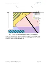
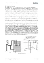
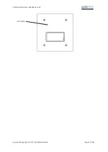
13 amp fused unswitched connection 
unit located close to the Automist 

Smartscan pump’s location


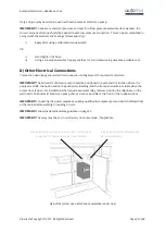
FP 200 fire resistant cable 

Separate 
circuit 

Содержание Automist Smartscan

Страница 1: ...an Handbook is designed to provide stakeholders with essential information regarding specification installation maintenance and commissioning of the Automist fire protection device Supersedes Automist...

Страница 2: ...l Obstructions 13 Example At Front of Built in Cupboard 17 Example Adjacent to an Opening 17 Example Close to a Wall 19 Example Over Worktop 20 Areas Not Required For Coverage 21 Indirect Coverage 21...

Страница 3: ...Copyright 2017 All Rights Reserved Page 3 of 64 S MA RT SC AN Post installation checklist Key points for installers and Building Control 48 Maintenance 51 Cleaning 51 Repair 51 Troubleshooting 51 War...

Страница 4: ...Automist Smartscan Handbook v1 2 3 Plumis Ltd Copyright 2017 All Rights Reserved Page 4 of 64 S MA RT SC AN INTRODUCTION TO SMARTSCAN...

Страница 5: ...ding children with reduced physical sensory or mental capabilities or lack of experience and knowledge unless they have been given supervision or instruction excluding children Automist Smartscan requ...

Страница 6: ...nsumer unit marked with an indicator sticker Watermist has a different principle of fire fighting to sprinklers which suppress fires by wetting surfaces and directly cooling the flames with large wate...

Страница 7: ...omist Smartscan supply label cable tie 3 single check valve 4 Filter 5 Stainless Steel Inlet Hose 6 Automist Smartscan Pump Unit 7 Quick connect with test point for pressure gauge 8 High pressure Outl...

Страница 8: ...demonstrate full compliance with the fire performance criteria of the BS 8458 2015 In short Automist is performance compliant with BS 8458 2015 despite not being fully prescriptively compliant which...

Страница 9: ...ance Concept Independently tested by Exova Warringtonfire and demonstrated to meet the fire performance standards of BS 8458 2015 and BS 9252 2011 the most up to date residential water mist and sprink...

Страница 10: ...Automist Smartscan Handbook v1 2 3 Plumis Ltd Copyright 2017 All Rights Reserved Page 10 of 64 S MA RT SC AN HOW TO SPECIFY SMARTSCAN...

Страница 11: ...BS 9991 2015 It is not acceptable to provide protection to only part of a single premise unless this is acceptable in accordance with Approved Document B or BS 9991 For details on the applications wh...

Страница 12: ...cations should be carefully chosen to reflect this fact Maximum visibility is most frequently but not always achieved by placing spray heads close to doorways on the handle side of a door where light...

Страница 13: ...hin specification for a three storey house with open plan ground floor and fire separation between ground and first floors Preferred Positions and Avoidance of Potential Obstructions A Preferred Posit...

Страница 14: ...the obstruction obstructs only the wall When the spray head is mounted close to an internal room corner it can be assumed that any obstruction between the spray head and the corner limits the spray he...

Страница 15: ...must be assumed to be only 90 due to potential obstructions either side of the spray head Note this is not a complete layout additional spray heads would be required to complete the scheme If the redu...

Страница 16: ...head would be required to complete the coverage For simplicity if a Preferred Position prevents the introduction of obstructions within 3m to the left or to the right the spray pattern can be assumed...

Страница 17: ...tion The proximity to a wall ensures that there is no potential for meaningful obstruction in the other direction Thus this is a Preferred Position Example Adjacent to an Opening A spray head placed n...

Страница 18: ...next to a pair of openings and an external corner Distance e must be less than 0 3m for the area to our right to be assumed free from potential obstruction If distance d is greater than 3m the area o...

Страница 19: ...o a Wall Figure 10 shows a spray head less than 1 5m from a wall In such cases the area between the head and the wall can be assumed unobstructed Figure 10 Spray head close to a wall Any object to the...

Страница 20: ...rved Page 20 of 64 S MA RT SC AN Example Over Worktop Provided that the worktop and cupboard heights are suitable the need to access a kitchen worktop guarantees its freedom from unplanned obstruction...

Страница 21: ...other dimension at the foot and head of every staircase and on both sides of every doorway Combustible obstructions will not routinely be placed in these zones as they would render a portion of the p...

Страница 22: ...other projects the Effective Shadow Area should not exceed 1 1 m2 per compartment The limit of 2 8 m2 per dwelling unit still applies If any contiguous zone of the Effective Shadow Area is out of the...

Страница 23: ...patterns Note the geometric shadow of the known chimney breast obstruction and the assumed 45 degree angle of coverage due to possible obstruction to one side of each spray head In Figure 14 the areas...

Страница 24: ...Figure 15 Shadow areas marked out yellow hatching In Figure 15 the shadow areas are marked In Figure 16 detail in Figure 17 the shadow area is reduced to the Effective Shadow Area by expanding the act...

Страница 25: ...erage in detail Coverage has been expanded in all directions by 0 3m Finally the Effective Shadow Area is measured If this room is a compartment then the Effective Shadow Area must be below 2m2 as thi...

Страница 26: ...tscan designs can be recommended by specifiers by following these recommendations however Plumis accredited installers are trained to specify install commission and maintain the Automist Smartscan sys...

Страница 27: ...pray heads may be permitted to be closer to the radiator when mounted on the same flat wall as the radiator but still no closer than 1 0m Real fire gas fire or electric heater with exposed heating ele...

Страница 28: ...If multiple Automist Smartscan units are to operate simultaneously a proportionately higher flow will be required A dedicated electrical supply circuit in fire resisting cabling such as FP200 This sh...

Страница 29: ...lled positioned and CE marked heat alarm BS 5446 2 compliant or by a heat detector EN54 5 compliant connected to a fire panelError Bookmark not defined Automist Smartscan is activated by feeding its t...

Страница 30: ...auses unacceptable disruption Wired lithium battery alarms with an integral relay are available correctly configured these report low battery to the Automist pump and cause it to go into a beeping err...

Страница 31: ...s version of Automist Smartscan will not function correctly if activated by smoke detection or a manual call point Use only fixed temperature heat detection Use with other types of detection could lea...

Страница 32: ...Automist Smartscan Handbook v1 2 3 Plumis Ltd Copyright 2017 All Rights Reserved Page 32 of 64 S MA RT SC AN INSTALLER GUIDELINES...

Страница 33: ...alling the Automist Smartscan Head C Connecting the water supply D Other electrical connections E The Automist Smartscan Controls F Commissioning and maintenance Notice Equipment you will need A suita...

Страница 34: ...wish to use a Henley Block to provide new tails to a second distribution board typically a 2 or 4 way unit The Automist Smartscan unit presents a part inductive load and therefore only type C breaker...

Страница 35: ...ww amazon co uk gp product B01GE3NDB4 ref pd_cp_107_1 ie UTF8 psc 1 refRID REA5Y9F0R C54QWVN72WM B Installing the Automist Smartscan Head Route the high pressure hose and a Plumis specification Smarts...

Страница 36: ...able does not result in movement or tension at the terminal block Slide the head into the rectangular hole 89 2mm wide x 117 mm high and fasten in place using the box old work mounting clips provided...

Страница 37: ...Automist Smartscan Handbook v1 2 3 Plumis Ltd Copyright 2017 All Rights Reserved Page 37 of 64 S MA RT SC AN Front plate...

Страница 38: ...nt are required so that the Automist Smartscan system can be shut off from the water main All such valves should be labelled with the included warranty void anti tamper sticker This enables clear iden...

Страница 39: ...ner Site Longer hoses require an increased internal diameter of 5 16 to account for the higher pressure drop IMPORTANT Plumis most recent guidance document on hose specification is more detailed and o...

Страница 40: ...Check Valve and the Flexible Hose OR Between the Flexible Hose and the Pump s inlet connector Prior to sealing the filter ensure the washer is lubricated using a suitable silicone based o ring lubrica...

Страница 41: ...can IMPORTANT The Automist Smartscan pump should be positioned in a safe and dry location where it is easily accessible the button will not be pushed accidentally and the front panel remains visible w...

Страница 42: ...g the short trailing Smartscan Head Cable at the rear of the pump to the cable that has been installed running to the Smartscan spray head Use pliers to crimp the Butt splice clips when connecting the...

Страница 43: ...is inaccessible Where required the loop should be cut and each end of the wire connected via FP200 or equivalent cable to a momentary action normally closed push button switch see diagram above The bu...

Страница 44: ...ivated by pressing the STOP button once The SYSTEM OK LED with then start flashing green on and off this indicates that ALARM MODE is activated In this mode you have a short time to test alarms in the...

Страница 45: ...asket to fasten the tool in place and put a bucket under the hose during the test procedure Commissioning Procedure 1 Unscrew the cap and connect the test hose and gauge to the test point adapter 2 Pr...

Страница 46: ...out which will disable it if the pressure becomes excessive so it is critically important not to leave an installed system with a high out of spec pressure By leaving an installed system with pressure...

Страница 47: ...circuit on the circuit breaker Label the heat alarm that triggers Automist Smartscan preferably near the test button Complete the installer commissioning label and affix to your Automist Smartscan un...

Страница 48: ...Inlet water must be connected and the valve left open WRAS approved isolation valves or equivalent are required so that the Automist Smartscan system can be shut off from the water main All such valve...

Страница 49: ...void dripping and Legionella High pressure hose should be protected by a fire resisting barrier and a fire resisting sleeve if exposed It is critically important that the high pressure hose locking pi...

Страница 50: ...Automist Smartscan Handbook v1 2 3 Plumis Ltd Copyright 2017 All Rights Reserved Page 50 of 64 S MA RT SC AN SMARTSCAN CARE...

Страница 51: ...ecommended Action Pressure does not consistently reach correct range too low during commissioning procedure Leakage between pump and Automist Smartscan head Check for leakage on the high pressure wate...

Страница 52: ...pump or spray head Pump or spray head damaged in transit The number of beeps or trills that the pump sounds when in fault mode is intended as a diagnostic Please count the beeps Two beeps is the norm...

Страница 53: ...y to commission the pump using the switch in lieu of a detector s test button If you can commission the pump using a light switch instead of a relay the fault is with the relay or relay wiring Power c...

Страница 54: ...turned to Plumis Ltd according to our return procedure The warranty on any replacement units will last for the remainder of the period of the original warranty Plumis Ltd reserves the right to offer a...

Страница 55: ...Automist Smartscan Handbook v1 2 3 Plumis Ltd Copyright 2017 All Rights Reserved Page 55 of 64 S MA RT SC AN Notes...

Страница 56: ...Automist Smartscan Handbook v1 2 3 Plumis Ltd Copyright 2017 All Rights Reserved Page 56 of 64 S MA RT SC AN APPENDIX A...

Страница 57: ...performance 6 1 Fire Tests When tested nozzle should suppress fires for 10 minutes for domestic or 30 minutes for residential Performance System run automatically for 30 minutes until stop button on...

Страница 58: ...engineered system so hydraulic calculations are not required No requirement to comply 6 6 Discharge Performance Flow for 64m2 Area of Maximum Operation Performance In this pre engineered system each s...

Страница 59: ...ferent principle of operation requires different locations as per Technical Handbook which must be followed typical for pre engineered systems Alternative coverage and positioning permits proven perfo...

Страница 60: ...pipe system 6 13 Additives Descriptive No additives used Not applicable 7 Installation commissioning and documentation Descriptive Frost protection only if water supply pipes to pump can freeze remain...

Страница 61: ...Automist Smartscan Handbook v1 2 3 Plumis Ltd Copyright 2017 All Rights Reserved Page 61 of 64 S MA RT SC AN...

Страница 62: ...Automist Smartscan Handbook v1 2 3 Plumis Ltd Copyright 2017 All Rights Reserved Page 62 of 64 S MA RT SC AN APPENDIX B...

Страница 63: ...e flat 9 4 3a Applicable Maisonettes having a floor level higher than 4 5 m above access level 9 5 2d Applicable Open plan flats 9 7 Applicable Flats where occupants are not capable of independent eva...

Страница 64: ...a buildings Figure C 1 Not applicable Protecting the base of an atrium or Ancillary accommodation Figure C 1 Not applicable Balcony escape where smoke retarding construction is provided to an atrium C...

Отзывы: