background image

25 November 2011

CF-4-2


FAULT CODE DESCRIPTIONS

Disconnect the motor plug M15. Run the Diagnostics again.

Fault code CF-002 (Open circuit) is displayed.

Y N 

Disconnect plug H.P3 from MD6DC “H”. Check wires for Short circuit across leads and tochassis, the orange wire 

M15 to H.P3-6 (violet) and the violet wire M15 to H.P3-7 (orange). 

There is a Short circuit. 

Y N

Replace MD6DC PCB ”H”. 

Repair wire Harness.

Replace motor M15.

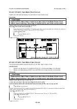
CF-001  CF-M15  Feed Motor Short Circuit

Fault Code indicates that the feed motor CF-M15 has a Short circuit 

Procedure

 WARNING 

Switch off the Main Power Switch and disconnect the Main Power Cord 

before disconnecting, removing or replacing any electrical components.

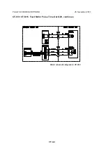
Block schematic diagram to CF-001 & CF-002

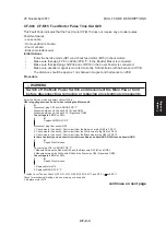
CF-002  CF-M15  Feed Motor Open Circuit

This Fault Code indicates that the Feed motor CF-M15 has an Open circuit.

Initial Actions

• 

Make sure that plug H P3 on MD6DC PCB “H” in the Booklet Maker is connected.

• 

Make sure that jack/plug J33/P33 and J32/P32 in the Cover Feeder is connected.

Procedure

Disconnect motor plug M15 and H,P3 from PCB “H”.

1. Check wire for Continuity / Short circuit the Orange wire from M15 to H,P3-7

2. Check wire for Continuity / Short circuit from Violet wire from M15 to H,P3-6

Is there Continuity and no short circuit between Orange and chassis/GND, Violet and chassis/GND

Y N

Replace/Repair wire Harness.

Disconnect the motor plug M15. Enter Service Mode and start Infeed motor (M15) in check motors. Measure between the 

orange wire M15 and the violet wire M15 (Motor power +/-).

The voltage is 30 VDC +/- 10%.

Y N 

Disconnect plug H.P3 from MD6DC PCB “H”. Measure between J3-6 and J2-7 (30V and GND).

The voltage is 30 VDC +/- 10%. 

Y N 

Replace MD6DC PCB “H”. 

Repair wire Harness.

Replace motor M15.

 WARNING 

Switch off the Main Power Switch and disconnect the Main Power Cord 

before disconnecting, removing or replacing any electrical components.

Содержание CF5030

Страница 1: ...25 November 2011 Subject to change COVER FEEDER CF5030 SERVICE MANUAL...

Страница 2: ...Page intentionally blank...

Страница 3: ...F 3 9 3 2 6 DRIVE MOTOR M16 ASSEMBLY CF 3 10 3 2 7 DRIVE SHAFT ASSEMBLY CF 3 11 3 2 8 PINCH ROLL SHAFT ASSEMBLY CF 3 12 3 2 9 PAPER PATH DSD DETECTION SENSOR Q30 CF 3 13 3 2 10 PAPER POSITIONING SENSO...

Страница 4: ...Page intentionally blank...

Страница 5: ...CF 1 1 25 November 2011 Installation 1 INSTALLATION PROCEDURE 1 1 INSTALLATION PROCEDURE Cover Feeder INSTALLATION PROCEDURE is located in the Booklet Maker BK5030 Service Manual 1 4...

Страница 6: ...Page intentionally blank...

Страница 7: ...November 2011 Preventive Maintenance 2 PREVENTIVE MAINTENANCE SCHEDULE 2 1 PREVENTIVE MAINTENANCE SCHEDULE Cover Feeder PREVENTIVE MAINTENANCE SCHEDULE is located in the Book let Maker BK5030 Service...

Страница 8: ...Page intentionally blank...

Страница 9: ...UNIT Replacement Adjustment CF 3 1 1 Remove Top Cover BK5030 Service Manual 3 3 5 2 Disconnect motor harness A x 2 3 Disconnect sensor harness B x 1 4 Disconnect fan harness C x 1 A B C Cover Feeder...

Страница 10: ...25 November 2011 CF 3 2 6 Remove screws D x 2 D Cover Feeder viewed from Booklet Maker rear side Cover Feeder viewed from Booklet Maker front side COVER FEEDER...

Страница 11: ...e brackets F and G 9 Lift the rear end of Cover Feeder and carefully remove the complete unit so that the shaft F comes loose from brackets F and G NOTE The shaft E must exit the cut outs in the brack...

Страница 12: ...Page intentionally blank...

Страница 13: ...November 2011 Replacement Adjustment CF 3 5 AREA F 3 2 AREA F 3 2 1 EMPTY BIN SENSOR Q31 1 Remove screw A x1 2 Gently lift out Sensor Q31 B and disconnect connector C x1 2 Remove Sensor Q31 B x1 A B...

Страница 14: ...25 November 2011 CF 3 6 1 Remove screw A x1 2 Gently lift out Sensor Q38 B and disconnect connector C x1 2 Remove Sensor Q38 B x1 A B 3 2 2 PAPER WIDTH SENSOR Q38 C AREA F...

Страница 15: ...SY AND PAPER SEPARATOR PAD 1 Remove the Feed roller assembly A by pressing it to the front side according to figure B 2 Lift out the rear side C of the Feed roller assembly 3 Remove the Paper separato...

Страница 16: ...ervice Manual 3 3 6 2 Remove Feed roller assembly 3 2 3 3 Disconnect Connector A x1 4 Remove screws B x3 5 Remove Feed motor M15 Replacement 1 Reverse the removal procedure 2 Enter Service mode 5 1 1...

Страница 17: ...Replacement Adjustment CF 3 9 AREA F 3 2 5 PAPER BIN LOW SENSOR Q33 B A C 1 Remove Rear Top Cover Booklet Maker Service Manual 3 3 6 2 Disconnect Connector A x1 4 Remove screws B x2 5 Remove Paper Bin...

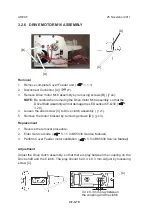
Страница 18: ...haft Assembly will not damage the LED sensor CF Q30 3 2 9 4 Loosen the allen screw C to Drive clutch assembly x1 5 Remove the motor bracket by removing screws D x3 B C D Replacement 1 Reverse the remo...

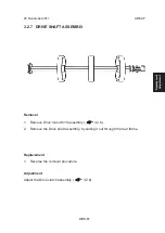
Страница 19: ...2 7 DRIVE SHAFT ASSEMBLY Removal 1 Remove Drive motor M16 assembly 3 2 6 2 Remove the Drive shaft assembly by sliding it out through the rear frame Replacement 1 Reverse the removal procedure Adjustm...

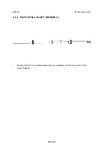
Страница 20: ...25 November 2011 CF 3 12 3 2 8 PINCH ROLL SHAFT ASSEMBLY 1 Remove the Pinch roll shaft assembly by pressing it to the rear side of the Cover Feeder AREA F...

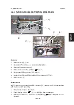
Страница 21: ...ve shaft assembly 3 2 7 5 Disconnect LED connector D x1 6 Loosen the LED nut E and slide off the connector x1 7 Remove LED F Replacement NOTE Make sure to install the LED connector C correctly so it w...

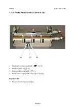
Страница 22: ...4 3 2 10 PAPER POSITIONING SENSOR Q32 1 Remove the lower paper path 3 2 10 2 Remove screw A x1 3 Disconnect connector B x1 4 Remove the paper positioning sensor Q32 C Replacement 1 Reverse the removal...

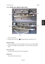
Страница 23: ...p Cover Booklet Maker Service Manual 3 3 6 Upper paper path 1 Remove Spring A on the Front and Rear side of the Cover Feeder x2 2 Remove screws B to Upper paper path x2 and remove upper paper path Low...

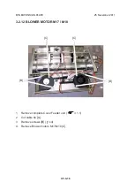
Страница 24: ...25 November 2011 CF 3 16 BIN EXTENSION PLATE 3 2 12 BLOWER MOTOR M17 M18 1 Remove complete Cover Feeder unit 3 1 1 2 Cut cable tie A 3 Remove screws B x4 4 Remove Blower motors M17 M18 C B C C B...

Страница 25: ...4 7 CF 008 CF Q31 Empty Bin Sensor Faulty CF 4 8 CF 009 CF Q30 DSD Sensor Faulty CF 4 9 CF 010 CF Q32 Paper Positioning Sensor Faulty CF 4 10 CF 011 CF Q33 Paper Bin Low Sensor Faulty CF 4 11 CF 012...

Страница 26: ...rcuit Initial Actions Make sure that plug H P3 on MD6DC PCB H in the Booklet Maker is connected Make sure that jack plug J33 P33 and J32 P32 in the Cover Feeder is connected Procedure Disconnect motor...

Страница 27: ...Q28 is toggling between 0 and 1 when rotating the Motor shaft Y N Disconnect plug F P6 from ADDON PCB F Measure between J6 13 and J6 19 5V and GND Measure between J6 18 and J6 19 Signal and GND The vo...

Страница 28: ...25 November 2011 CF 4 4 CF 003 CF M15 Feed Motor Pulse Time Out Q28 continues Block schematic diagram to CF 003 FAULT CODE DESCRIPTIONS...

Страница 29: ...on MD6DC PCB C in the Booklet Maker is connected Make sure that jack plug J33 P33 and J32 P32 in the Cover Feeder is connected Procedure Disconnect motor plug M16 and C P2 from PCB C 1 Check wire for...

Страница 30: ...een J6 4 and J6 22 5V and GND Measure between J6 21 and J6 22 Signal and GND The voltage is 5 VDC 10 Y N Replace ADDON PCB F Disconnect plug from sensor Q29 1 Check wire for Continuity Short circuit f...

Страница 31: ...MD6DC PCB H 1 Check wire for Continuity Short circuit from the Orange wire at plug I P1 1 to H P2 5 2 Check wire for Continuity Short circuit from the Violet wire at plug I P1 2 to H P2 11 Is there C...

Страница 32: ...for Continuity Short circuit from the Black wire at plug Q31 to F P6 9 Is there Continuity and no short circuit between Red and chassis GND White and chassis GND Y N Repair Wire Harness Replace sensor...

Страница 33: ...VDC 10 Y N Replace Addon PCB F Measure between F P1 2 and F P1 5 5V and GND in the F P1 plug The voltage is 5 VDC 10 Y N Replace Addon PCB F Disconnect plug from sensor Q30 Check the white wire from...

Страница 34: ...ontinuity Short circuit from the Black wire at plug Q32 to F P6 12 Is there Continuity and no short circuit between Red and chassis GND White and chassis GND Y N Repair Wire Harness Replace sensor Q32...

Страница 35: ...it from the Black wire at plug Q33 to F P6 25 Is there Continuity and no short circuit between Red and chassis GND White and chassis GND Y N Repair Wire Harness Replace sensor Q33 Block schematic diag...

Страница 36: ...lack wire at plug Q38 to F P6 9 Is there Continuity and no short circuit between Red and chassis GND White and chassis GND Y N Repair Wire Harness Replace sensor Q38 Block schematic diagram to CF 012...

Страница 37: ...t Code indicates that during a run the Paper path DSD Sensor Q30 was not blocked within timeout Initial Actions Make sure that the Paper path DSD photo transistor sensor and the Paper path DSD LED sen...

Страница 38: ...lacing any electrical components CF 205 CF Q32 Paper Position Sensor Activated too long Fault Code indicates that during Run the Paper positioning sensor Q32 was blocked exceeding timeout Initial Acti...

Страница 39: ...and M18 BK 5 1 Check for mechanical bindings broken missing or loose parts CF 207 CF Q30 DSD Sensor Not activated when Paper Position Sensor Q32 is activated Fault Code indicates that Q30 is Not activ...

Страница 40: ...ocedure 1 Inside Cover Feeder Check Q30 Q31 Q32 Q38 M15 M16 M17 and M18 BK 5 1 Check for mechanical bindings broken missing or loose parts 2 Go to CF 012 CF 503 Empty Bin idle Fault Code indicates tha...

Страница 41: ...Service Tables CF 5 1 25 November 2011 5 SERVICE TABLES 5 1 SERVICE TABLES Cover Feeder SERVICE TABLES is located in the Booklet Maker BK5030 Service Manual 5...

Страница 42: ...Page intentionally blank...

Страница 43: ...Feed motor CF 6 2 N5 CF M16 Drive motor CF 6 2 O5 M5 CF M17 M18 Blower motors CF 6 3 N5 CF Q31 Empty bin sensor CF 6 3 Q6 CF Q30 Paper path DSD detection sensor Phototransistor CF 6 3 P6 CF Q30 Paper...

Страница 44: ...25 November 2011 CF 6 2 ELECTRICAL COMPONENT LIST 6 1 1 REAR VIEW CF M15 CF M16 CF Q33...

Страница 45: ...25 November 2011 Detalied de scription CF 6 3 ELECTRICAL COMPONENT LIST 6 1 2 OUTFEED VIEW CF Q31 CF Q30 Phototransistor CF Q32 CF Q30 LED CF M17 M18 CF Q38...

Страница 46: ...Page intentionally blank...

Страница 47: ...activated the feed and drive motors runs a short distance lon ger and then stops The cover feeder is now in ready mode During automatic operation the copier sends a start signal a manually fed set nee...

Страница 48: ...Page intentionally blank...

Страница 49: ...CF Spec 1 25 November 2011 Specification SPECIFICATIONS SPECIFICATIONS Cover Feeder SPECIFICATIONS is located in the Booklet Maker BK5030 Service Manual SPECIFICATIONS...

Страница 50: ...Page intentionally blank...

Страница 51: ...CF Wir 1 25 November 2011 Wiring WIRING Cover Feeder Included in wiring diagram to BK5030 See separate document...

Страница 52: ...Page intentionally blank...

Отзывы:

Похожие инструкции для CF5030